Lab Notes 11/2/2012

I got the building permit from the city. Woo hoo! Most of my garage is already boxed up; the plan now is to haul it all out to a self-storage place and invite family over to build a partition wall in exchange for obligatory beer and pizza. Hopefully I can get this all accomplished before the end of the year.

In other news... have you ever accidentally won an online auction? Yeah, me too. I was going to ask Santa to bring me a new Rigol DS1102E oscilloscope this year. (Because I've been a good boy and all.) The 1102 is a 100MHz digital scope. Well, I was browsing through an online surplus auction and found an auction for a lot that included a 275MHz HP 1725A 'scope. The opening bid was only $30. There were no bids. What was there to lose? I might, just might, win this little auction in a hidden corner of the 'net and walk away with a $30 scope!

Yeah, well, you know the rest. I paid a little more than $30 for the lot (but not more than I can afford to lose if the equipment doesn't work). I ended up with a rather eclectic haul.

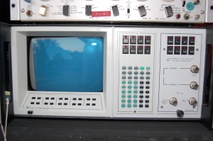
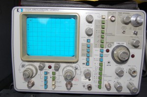
First up we have the HP 1725A. This is a 1970's-era scope I believe, and the controls are wonderfully analog. That dial on the top right, for instance.. the Time Interval one? The outer ring is the tens digit and the inner ring is the ones digit. The outer ring snaps to the next digit as the inner ring is rotated. How romantic!

I do hope that it works, or that it can be brought to working order relatively inexpensively. I haven't yet plugged it in.

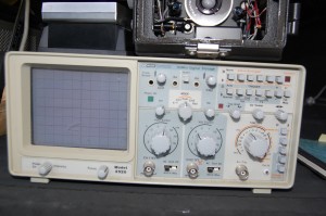
The second item in the lot is a 20MHz digital storage oscilloscope, a BK Precision model 2520. I haven't been able to find out much about this unit from online searches. It's significantly lighter than the HP; as a digital storage scope I'm sure it uses much more modern components.

The next item is a Data Precision Data 6000 Model 620. I have absolutely no idea what this is or what it does.

A quick Google search suggests that this is a waveform acquisition, display, and digital analysis system. I apparently have a Data Precision 6000 with a model 620 plug-in. It apparently does 8-bit A/D conversion at up to 100MSPS and sports a whopping 48K of memory. Without a manual I'm afraid this might be difficult to use. Anyone able to point me to one? My quick searches have turned up nothing.

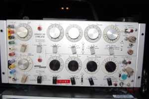
The last part of this lot is the most fascinating. This is a Grass S88 Stimulator.

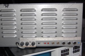
I have no clue what this thing is supposed to stimulate. (Muscles, maybe? It is surplus from a teaching hospital.) Look at those wonderful switches and dials! If I ever shoot a low-budget 60's horror flick, this thing is going to have center stage in the mad scientist's laboratory. I love the look of this thing-- those long bat-handled toggle switches, the fat chunky selector switches, those dial indicators, the (presumably) neon lights... very very cool. Check out the back panel:

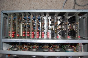
All those louvers for heat to escape. You don't think there might be tubes in there, do you? Well, there's only one way to find out. The top panel is held on with six screws. I popped that off and, alas, no tubes. But lots of discrete power electronics:

It's rather incredible to think that most of the electronics on those nine plug-in cards on the left could probably be replaced by a two dollar microcontroller today.

Aha! Found a Google reference. From the manufacturer's website:

The S88 is a dual output, general purpose stimulator for nerve and muscle stimulation procedures. Applications extend from single cell to entire muscle stimulation. The two output channels can be operated independently or synchronized to produce complex paradigms. The outputs are non-isolated constant voltage positive pulses. New features include computer compatibility and flexibility of synchronization circuits. The synchronous inputs and outputs are TTL, 5 volt, PC compatible. A rear DB25S connector permits external analog control of the timing circuits. Optional Stimulus Isolation Units are available for applications requiring isolation and/or constant current.

It appears that this company is still selling similar units. I'm sure I have absolutely no use for this, but I'm equally sure that I'll hang on to such a beautiful device (perhaps occasionally practicing an evil "muwahahahaaa!" as I walk by it) in the hopes that I'll eventually find something useful to do with it.
Lab Notes 10/16/2012

I've alluded to this earlier, but the truth is that the Hacker Workshop doesn't really have a workshop. Today I applied for a building permit from the city to partition part of my garage into an air conditioned workshop. I hope to get this done by the end of the year.

The wife took a part-time job recently, so I've been spending a lot of time with the kids which has cut into my hacking time.

Getting Started with the ARM GCC Compiler on Windows, Part 5: Debugging with OpenOCD

In part 1 of this tutorial series, we installed the GNU ARM GCC toolchain and the Eclipse IDE in order to develop for our ARM microcontrollers. In part 2, we configured the correct compiler and linker settings to get the STM32F0DISCOVERY demo code to build. In part 3, we pared down the demo project into a template to use for all of our future projects for the STM32F0 chip. And in part 4, we build a 'BlinkyLED' program from the template that uses the two LEDs and the user button on the STM32F0DISCOVERY board.

The previous tutorials are all you need to get things up and running on your STM32F0DISCOVERY board... as long as your code works the first time. If your code doesn't work the first time (like, say, my code), you'll want to add some debugging features to your build environment. If you're accustomed to writing code on a desktop computer using a modern IDE such as Visual Studio, you're used to being able to single-step through your code in the debugger from the source code, you're used to examining and modifying the contents of variables when you've broken into your code execution, and you're used to setting breakpoints in your source code. This functionality is (relatively) easy to accomplish on a desktop computer, but things get pretty tricky when trying to do the same things on an embedded platform. The STM32F0 chip has 64K of program space. Shoehorning a complex debugger into that code space along with your application code can be problematic. Continue reading Getting Started with the ARM GCC Compiler on Windows, Part 5: Debugging with OpenOCD

Driving Servos with the STM32F0Discovery

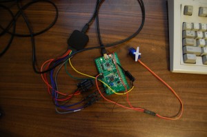
My code appears to be working. I'm driving one of the cheap Chinese servos I bought from the STM32F0DISCOVERY board. I've verified with the Saleae Logic probe that all 8 channels are giving output, and I have one servo wired up and moving. You'll have to take my word on the motion part; I'm not going to dig out the camcorder and edit video just to show a servo horn moving. Note that I'm currently powering the servo from the host computer's 5V USB bus, and the servo's control pin is connected to the 3.3V output of the STM32F0. This probably isn't ideal conditions for driving this servo, but the quick-and-dirty test shows that it's working.

As always, click on the thumbnail for the full sized picture.

I apologize for the low-light photo; using the flash produced too much glare from my desk.

I'll eventually share the code; right now it needs a lot of cleaning up before it's ready to share.

Lab Notes 9/29/2012

I'm still playing with the STM32F0DISCOVERY board. I've written some code that uses timers TIM2 and TIM3 to produce PWM outputs suitable for driving radio-controlled servos. The timers can produce the required waveform with no intervention from the CPU. So once the timer is correctly configured and the servos are put in the desired position no further attention from the software is necessary.

I found that doing float or uint32_t arithmetic seems to haul in large parts of the newlib library, which bloats my code quite a bit. Just initializing the servos takes 11K of code space! I need to look into that further and see what can be done to tame this code bloat.

I was going to write a tutorial on using OpenOCD to debug code on the chip. Dr. Al-Hertani has such a tutorial here, although my results weren't as positive as his. I find that I have to use the telnet session to OpenOCD and manually issue a 'reset halt' command before each debug session. I don't know why.

I added the Subclipse package to my installation of Eclipse to put my code under source control. I feel much better about experimenting with my code now.

Since my code is under source control, I may rebuild the VM that I'm using to host my build environment and see if I can fix the issues with OpenOCD.

I turned on the compiler warnings "implicit conversion warnings" in my projects. These code issues have bitten me before so having the warnings on is nice. Unfortunately, many lines in the Standard Peripheral Library cause these warnings to be triggered. I edited some of the library files with the appropriate #pragma to suppress these warnings. For example:

[cce]#pragma GCC diagnostic push
#pragma GCC diagnostic ignored "-Wconversion"
╥╥╥╥╥╥*(__IO uint16_t*) tmp = Data >> 16;
#pragma GCC diagnostic pop[/cce]

I've been at the computer enough today. I think I'll see if I can find some college football on the television.

Yet Another Low-Cost Dev Board

Freescale joins the bevy of companies offering low-cost ARM dev boards with the Cortex-M0+ based "Freedom" dev platform.

Based on the Kinetis L series KL1 and KL2 chips, this $12 board offers the usual slew of peripherals, an onboard debugger, and various goodies including USB, an accelerometer, and a tri-color LED. A touch slider is included as well, and the chip supports updating firmware via a simple drag-and-drop USB mass storage interface, which is cool.

Interestingly, Freescale designed the board to be pin-compatible with Arduino shields. This is surprising news from a company that has been known to be very unfriendly to hackers/makers.

So I've got my STM32F0DISCOVERY, my STM32F4DISCOVERY, my LPCXpress board, my Stellaris M4F should be here soon, now there's the Freescale part (that I may or may not order), and I haven't even ordered a Raspberry Pi yet.

How many other low-cost ARM dev boards are there? How are manufacturers going to differentiate their products if this trend continues?

WordPress, CodeColorer, and Leading Whitespace

If you've ever hosted a geek-oriented blog, you're familiar with this problem. You have some code that you want to share with your audience. You copy the nicely formatted code from your source file, you paste it into your blog, and when you preview your post, your code looks like mud. HTML in general, and the WordPress post editor in particular, don't play nice with leading spaces in text. Text that was nicely formatted before it was pasted into a blog post ends up having all the lines mashed up against the left margin in an barely readable mess.

I searched for a solution to this problem and found that there really is no good solution. So I decided to invent my own. It's a hack, but it's a solution. Here's what I do to paste code into a WordPress blog entry, and have CodeColorer display it as I intended:

  1. Install the CodeColorer plug-in on your WordPress site
  2. Edit the source code for the plug-in to change a special character (I use ) into the escaped HTML string  
  3. When you want to put code into a post, copy it from your source file into a text editor. Replace leading spaces with your special character. Copy the resulting text and paste it into your WordPress post
  4. WordPress won't strip out the leading spaces in your code because, well, they're not spaces any more
  5. When your audience views your post, CodeColorer will take all your special characters and send them to the web browser as non-breaking spaces
  6. The web browser will display the leading spaces as you intended

Now, I admitted up front that this is a hack of a solution. But... and this is the key point... it works!

It's hard to argue with success. Here's how to do it. Continue reading WordPress, CodeColorer, and Leading Whitespace

Getting Started with the ARM GCC Compiler on Windows, Part 4: Our First Real Project

If you've been following along, in part 1 of this tutorial we installed the free ope-source ARM GCC toolchain, GNU Make, and Eclipse. In part 2, we configured Eclipse to build the demonstration project that ships on the STM32F0DISCOVERY board. In part 3, we pared down the demo project to become a baseline template for future STM32F0 projects.

In this tutorial, we'll start with the template project we created in part 3, and build our first application for the STM32F0DISCOVERY board. This will be a simple project: it will blink the green LED. When the user button is pressed, it'll blink the blue LED instead. Though the project goals are simple, it nevertheless is a good learning exercise. Continue reading Getting Started with the ARM GCC Compiler on Windows, Part 4: Our First Real Project

Lab Notes 9/19/2012

I spent some time today writing a simple "BlinkyLEDs" program to demonstrate how to use our template project. I spent a few frustrating hours trying to determine why the LEDs wouldn't light up. It turns out that you must enable the clock to the GPIO peripheral before initializing the pins.

I should have a writeup on this project by the end of the week. It probably won't happen tonight.