I had given up all hope of receiving my AVC circuit boards and had convinced myself that they had become forever lost in the mail. And wouldn't you know, today they show up. Ten circuit boards when I only need one.
Seeing the actual board at 1:1 scale it's clear, even before I take out some magnification, that I was too aggressive trying to shrink down the size of this board. I've got pads too close to traces, and jumpers too close to other pads, and I'll be surprised if it works at all.
Not that that'll stop me from trying, of course.
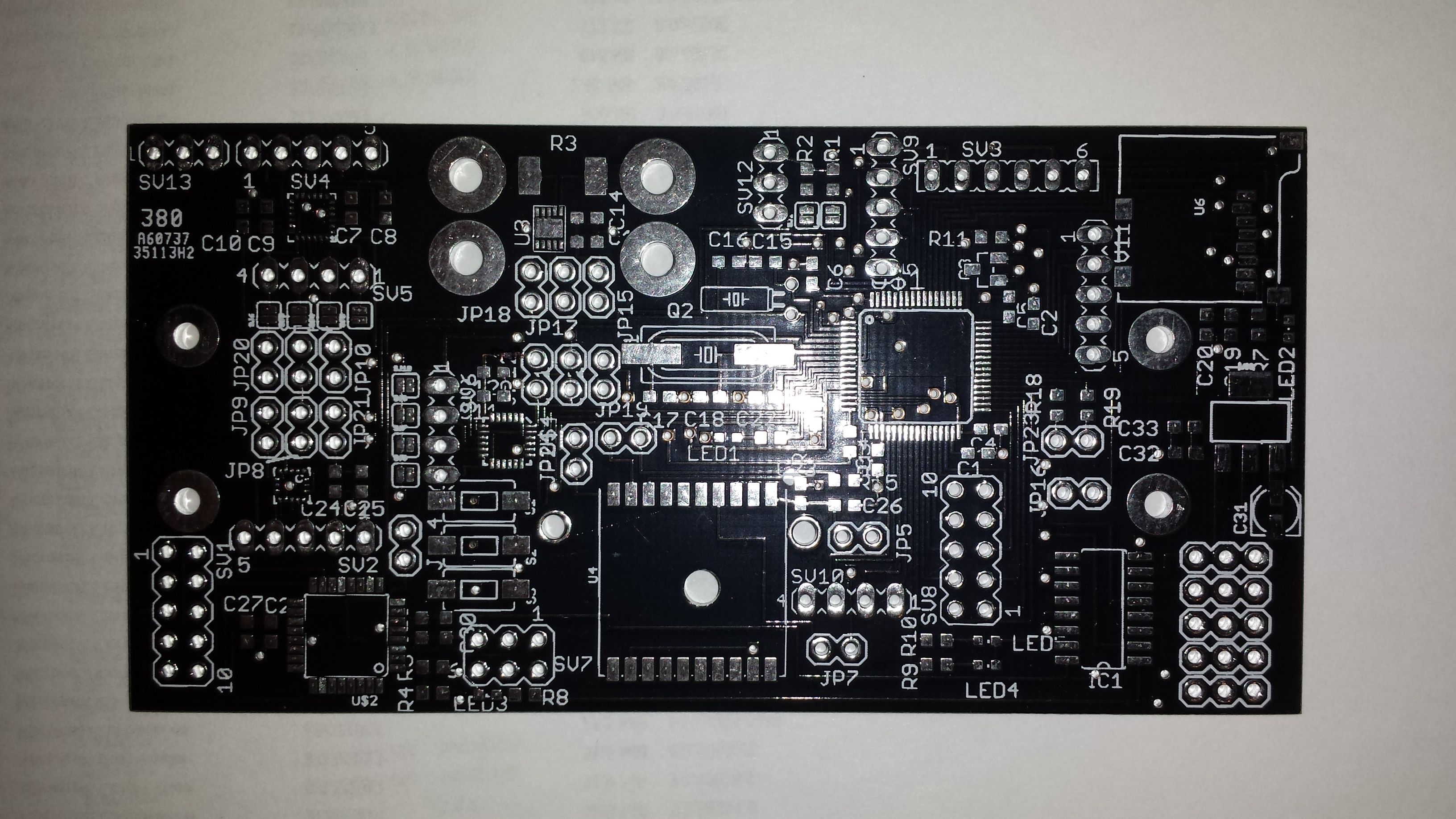
My apologies for the glare from the flash on the camera. Let's take a tour of the board so you can all see just how awful I am at circuit board layout, shall we? You should be able to hover your mouse over the pic below to get popups that describe each part of the board.
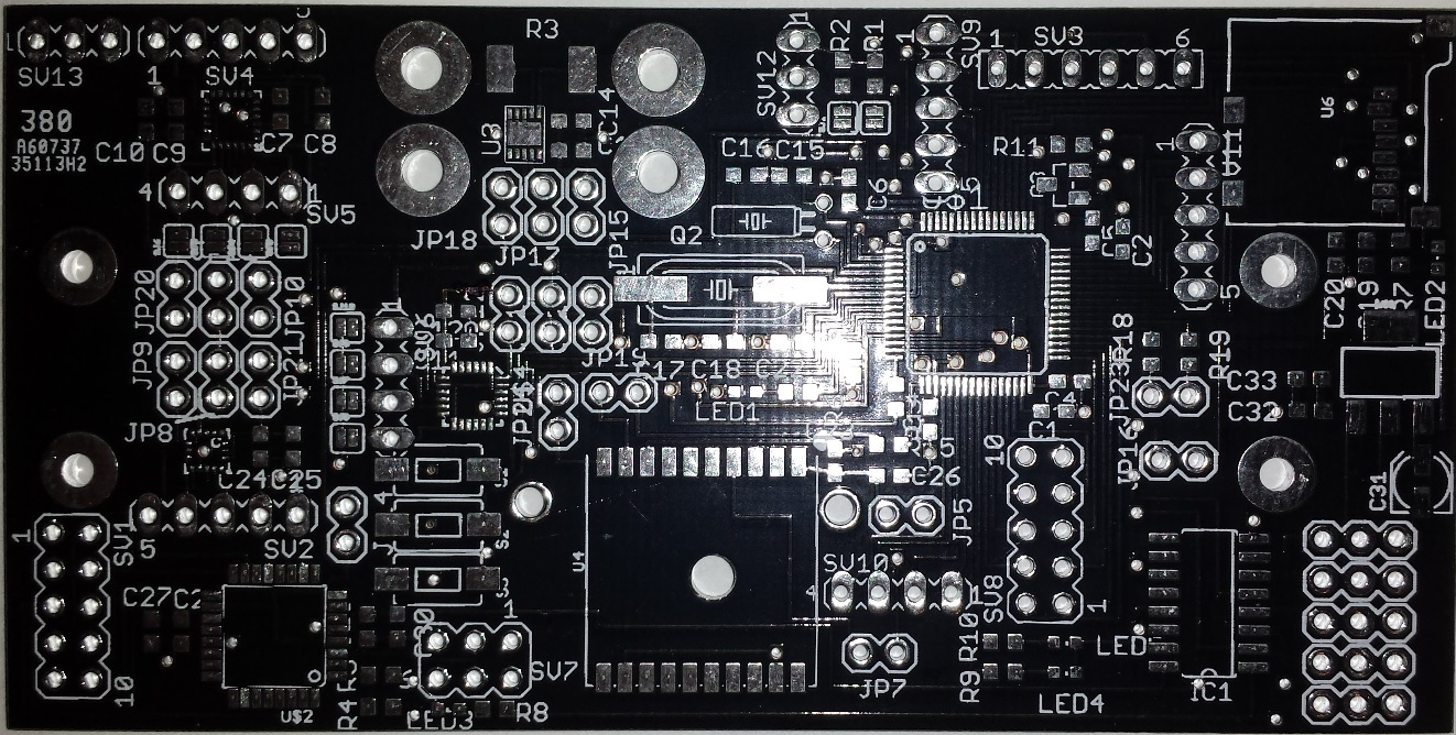
Starting at the upper right we have a micro SD card slot. Beneath that is a voltage regulator that will take battery power from the Battery Eliminator Circuit (BEC) and step it down to the 3.3V required by the logic parts on the board. Beneath that are five three-pin headers that interface to the radio and to the car: from the radio, inputs for throttle, steering, and manual/auto control. To the car: throttle and steering. To the left of that, a sixteen pin MUX to switch throttle and steering inputs from the autopilot and the radio to the car. Left of that are a few headers to break out unused pins from the microcontroller for "future expansion" or something.
The large square part over the hole in the board is for the Adafruit Ultimate GPS module. The chip in the lower left is an ATTINY88 that is running the R/C MUX code. Three pushbuttons sit between the GPS and the ATTINY88.
Above the buttons is a MPU-9250 inertial measurement unit. Above the ATTINY88 is a MAX21000 ultra high accuracy gyro. Above that (above two sets of headers) is a ST LSM9DS0 IMU. Why do I have three chips that do the same thing on my board? Well, because I don't know how well they compare against each other, and by having all of them on the board I can choose in software which set(s) of inputs to use.
The four large pads on the top left-center of the board are to feed power from the battery to the board and then on to the motor speed controller/BEC. R3 is a 750 uOhm resistor to do current sensing in conjunction with the PAC1710 chip snugged in there.
To the right of the crystals is the STM32F405 microcontroller, which is the brains of the circuit. The header to the left of the SD card is the SWD programming header for the STM32F4 chip. The 10 pin header in the lower left is the programming header for the ATTINY88. The other headers are there to bring unused pins on the STM32F405 to a usable location. The two pin jumpers scattered around the board are to disconnect the SCK and SDA lines from each of the chips on the I2C bus, and to disconnect power from each of the chips, for debugging.
Regrettably, I have to admit that I just don't have time to get my bot ready for this year's AVC. Between work and family commitments (and the fact that my solder paste stencil still hasn't arrived from China!), I just don't have the time to dedicate to this project. So curse you, Data Bus! You win this round! But THWSBot will be back in 2015!
http://infoblog.win/
scroll. Go to Code Form
55 thousand Greek, 30 thousand Armenian
antiquities. These are the Egyptian papyri
the best poets of his era and
“Julia’s Garland” (fr. Guirlande de Julie)
manuscripts underwent in the Middle
“Julia’s Garland” (fr. Guirlande de Julie)
from lat. manus – “hand” and scribo – “I write”) ]
among them acquired “Moral
(palimpsests). In the XIII-XV centuries in
(palimpsests). In the XIII-XV centuries in
from lat. manus – “hand” and scribo – “I write”) ]