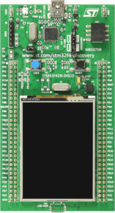
We're going to be working with the STM32F429 Discovery board. There are two variants of this board and it's spelled different ways in different places, but for our purposes they're all the same. (The differences between the two are solely in the ST-LINK debugger portion of the board.) In case you haven't seen it, the board looks like this (as always, click on the thumbnail for a full-size image):
Let's kick off our tutorial of the STM32F429-DISCOVERY board by talking about the microcontroller that's soldered to it: the STM32F429ZIT6.
Now, the first thing you should do when learning about a new electronics part is download the datasheet for the chip. The datasheet has tons of information in it, some of which you won't really need, much of which you will. The first page of the datasheet gives a nice summary of the chip.
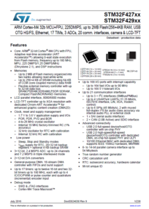 The summary page has a number of bullet points that talk about the CPU core, the memories, and the peripherals that are in the chip. Let's look at some of these features, and I'll give you my commentary as a free bonus.
- ARM Cortex M4 CPU Core: This is probably the thing you should be least concerned with. As a programmer, you're going to write your code in a language such as C, and the compiler will create code that runs on the microcontroller. Whether that microcontroller has an ARM core, a MIPS core, an AVR core, or a PIC core, your code will run on your chosen platform because you chose a toolchain to target that platform. Most of us couldn't care less what engine is under the hood as long as our code runs.
- A Hardware Floating-Point Unit: Okay, this is pretty cool. If your code does heavy floating-point math, having FPU hardware is going to be much faster than doing the floating point work in software, which is what the compiler does if your hardware doesn't have an FPU.
- Flexible Clock Sources: The STM32F429 has two primary clock domains: the high-speed clock that drives pretty much everything on the chip, and the low-speed clock that's designed primarily to drive the realtime clock (RTC). Both can be sourced from an on-chip oscillator (16MHz high-speed, 32kHz low-speed) or from an external crystal. The internal oscillators are not as accurate as using an external crystal.
- A Maximum 180MHz Clock: While a clock cycle is not necessarily a clock cycle when you compare different architectures, 180MHz is still pretty fast for microcontrollers. You'll be able to do a lot of number crunching in a short period of time with this chip.
- 2MB Flash ROM: Means you can write big, nay, huge programs and they'll fit in the chip. I doubt I'll ever write code that requires this much space, but it's nice to know that the space is there.
- 256 + 4k RAM: Again, lots of space is nice. Having 256K of RAM on a microcontroller is quite generous. (I first started programming in PIC chips that had only 128 bytes of RAM. This chip has 2,000 times that!) The "plus 4k" is RAM that is battery-backed and is retained in standby mode. This can be useful for low-power battery-powered applications.There's also 64K of "core-coupled memory"
- External Memory Controller (FSMC): If you really need lots of RAM (say you're driving a large graphics LCD display and you need lots of RAM for a framebuffer), this controller can interface with external SDRAM, SRAM, PSRAM, NOR Flash, and NAND Flash. It supports a data bus width of 8, 16, or 32 bits. The controller's memory space is divided into four 64MB banks, for a total of 256MB external memory that can be addressed. That's a lot of memory for a microcontroller, and if you have an application that could honestly make use of that much RAM, I'd love to hear about it!
- LCD Interface and Controller: Need a graphics display for your next project? The STM32F429 can drive it.
- Realtime Clock: Keeps track of time-of-day and calendar so you don't have to. Will run on a backup battery even when the CPU is asleep. (Or not powered.)
- ADC: A 12 bit, 2.4 megasample per second analog-to-digital converter with up to 24 channels.
- DAC: Two 12 bit digital-to-analog converters.
- DMA: A pretty powerful and flexible DMA controller will shuttle data between various memory regions for various peripherals without the need for the CPU's intervention.
- Timers: A whole passel of 'em. Up to 17 hardware timers, from basic counters up to super double-throwdown fully featured whizbang timers. With sprinkles.
- GPIO: With the larger packages, up to 168 I/O lines. On our 144 pin LQFP part, we have fewer I/O's than that.
- I2C: Up to 3 I2C interfaces (depending on package)
- SPI: Up to 6 SPI interfaces (depending on package), two of which can support I2S
- UARTs: Up to 4 UARTs
- CAN: If you're into automotive interfacing (and the STM32F429 series would not be a bad choice at all for that application), the chip has 2 CAN interfaces.
- SDIO: A seeming afterthought on the summary page of the datasheet, the STM32F429 supports a full 4-bit wide data path for SD memory cards.
- USB: The chip has 2 USB ports. One is a full-speed port (12Mbps) and one high-speed (480 Mbps). Both support host, device, and OTG modes. The high-speed port does not have a PHY (physical layer interface) on the chip, which necessitates an additional component if you want to use that feature.
- Ethernet: Yes, Ethernet. Like the high-speed USB port, the Ethernet port has a MAC but no PHY, so to use Ethernet you'll need an outboard PHY chip.
- Camera Interface: I honestly don't know much about this.
- Hardware Random Number Generator: Useful if you need truly random numbers, as many cryptography applications would.
That, my friends, is quite a list of features. And all this is packed into a chip that you can purchase for $15 in single-unit quantities. Living in the future rocks!
Like most digital chips these days, the STM32F429 is not 5V tolerant. The power supply voltage for the chip needs to be 1.7 to 3.6V. The DISCOVERY board has an onboard voltage regulator that generates 3.3V from the 5V USB connection.
In the next tutorial installment, we'll look at the features on the DISCOVERY board. Then we'll set up a development environment to start programming it!