Well, the move-out date on my self storage unit is fast approaching, which has had me motivated to finish the shop.
As of tonight, all (well, almost all) of the insulation is up and the workshop is (mostly) ready for drywall. I've had a few contractors out to the house to bid on hanging the drywall. So far, none of the bids have been low enough to convince me outsource this work. (Which is rather disappointing. Cheap labor is not hard to find in the Dallas area.)
Hacker Dad and Hacker Father-in-Law have volunteered to come over on Saturday to hang drywall, provided I have everything ready to go. While I really, really don't want to do this job myself, I can be an inveterate cheapskate and the relative merits of build-vs-buy are favoring a sore body this weekend.
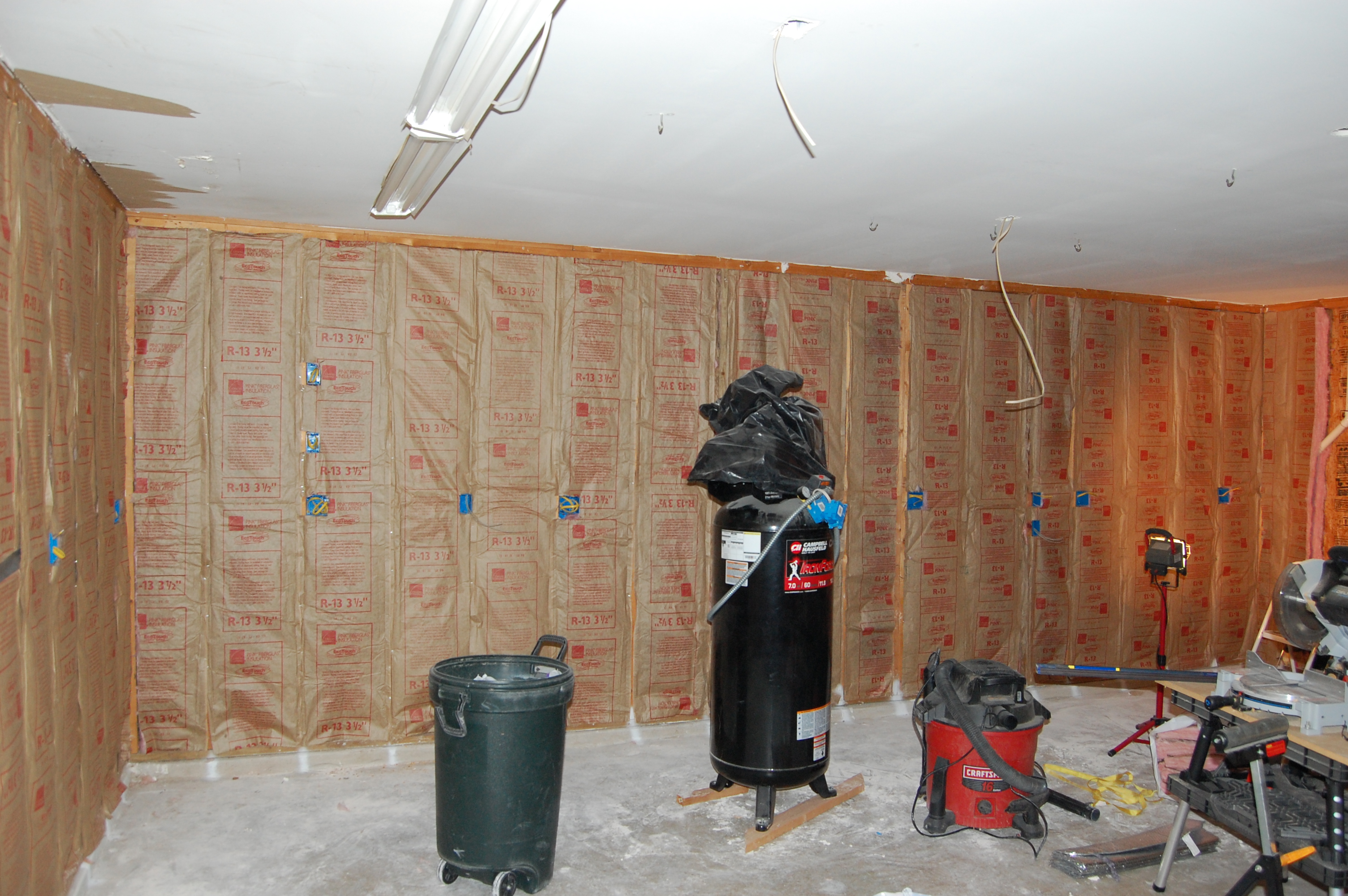
Here are some pics of the current state of the workshop. As always, click for a full size version.
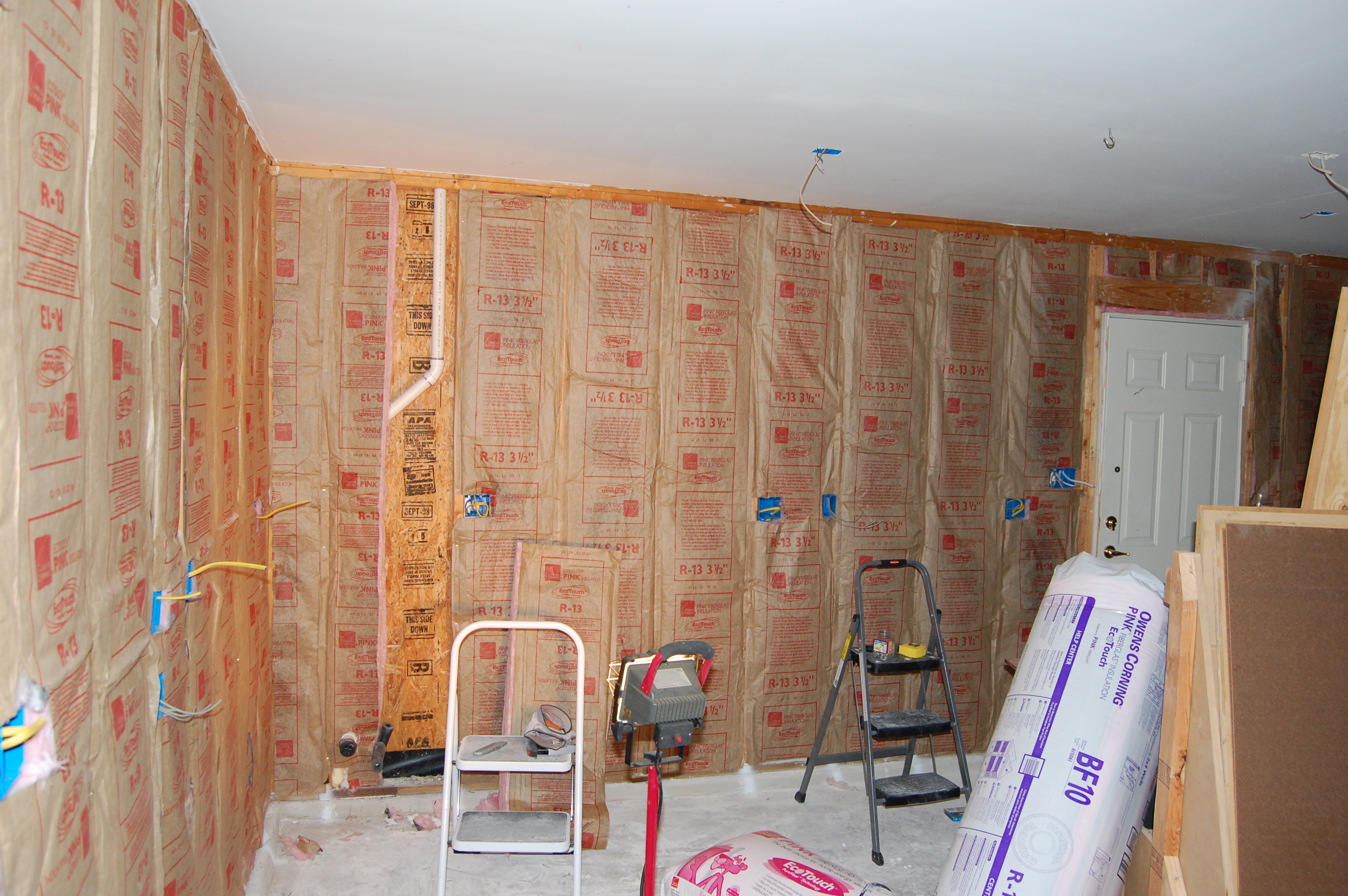
First wall, fully insulated. Framed out for an exterior door with paint on the floor to tell me where to tear out drywall in the future.
Back wall, fully insulated. Location of studs marked in white paint on the concrete lip at the floor.
Third wall, almost fully insulated. That cavity with the plumbing is larger than a 16 inch on center cavity. I quit to come inside and spend time with the kids.
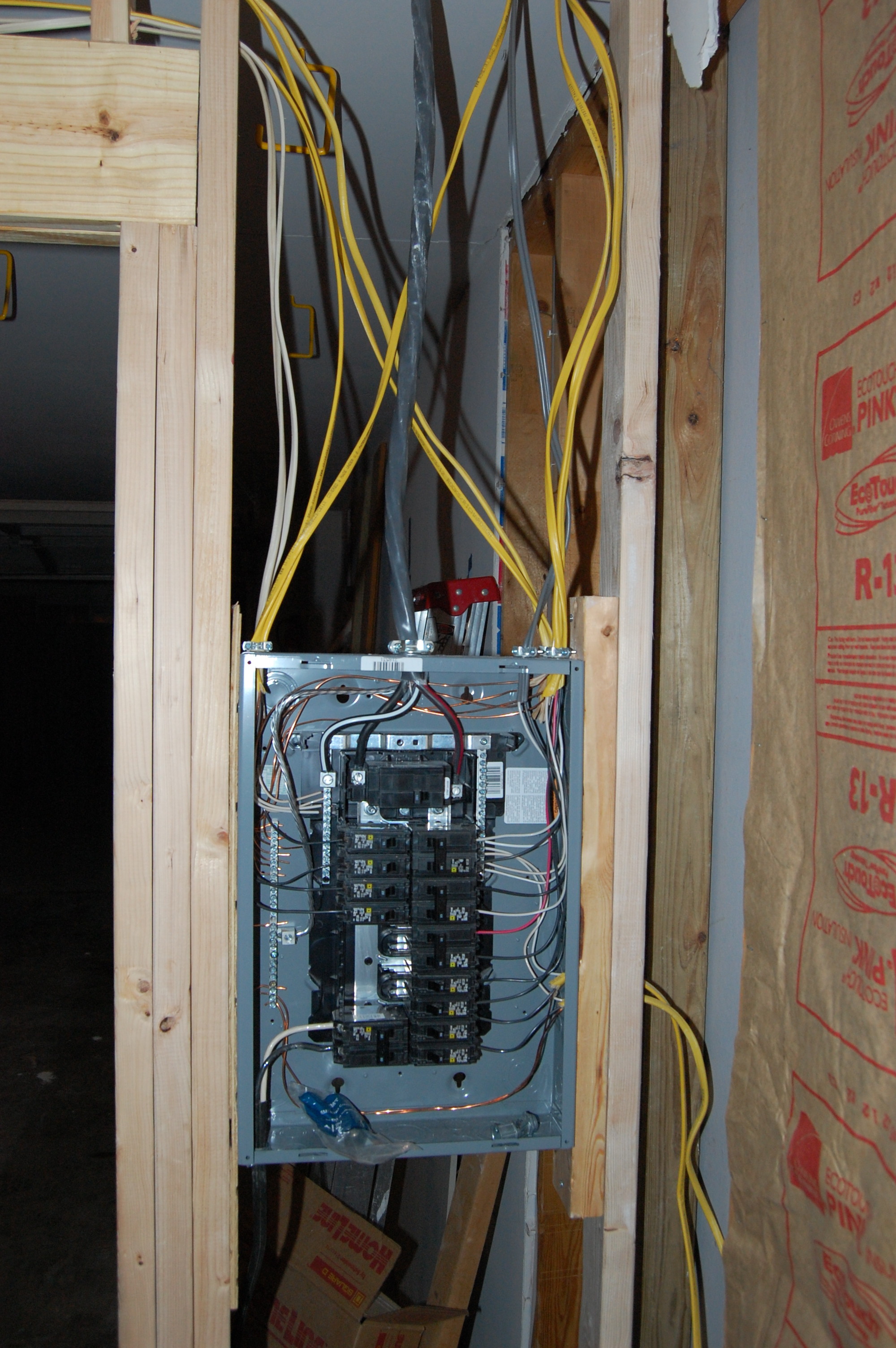
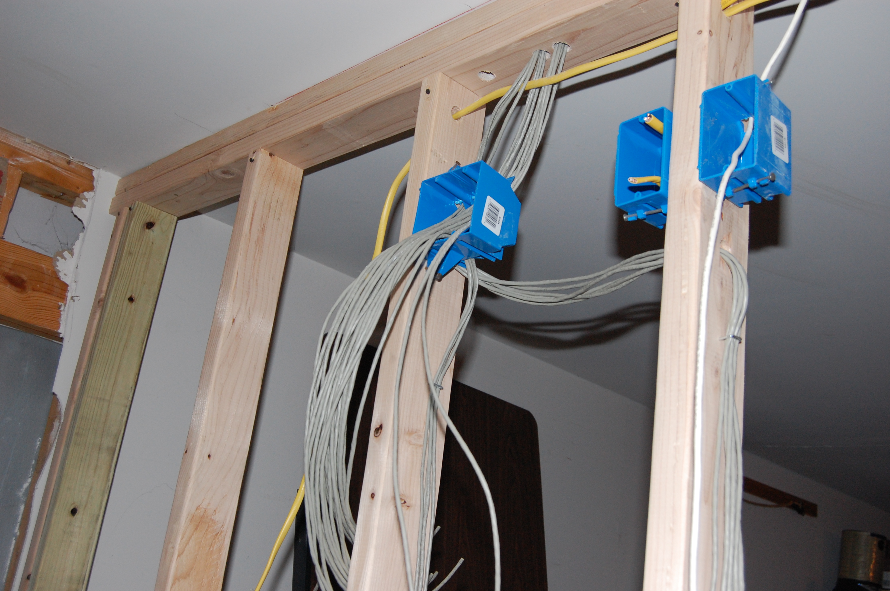
Subpanel will be fed from a 90 amp breaker on the main panel. Many thanks to Hacker Brother, who helped me run that 2-2-2-4 aluminum cable through the attic.Is 24 hardwired Cat5 runs too many for a 21 x 21 foot workshop? Yeah, that might be overkill. The white cable is Cat5 to the patch panel in the house where the internet connection is. The outlet box is for a network switch and wireless access point.
Supermodel Wife took the kids to her parent's house today, leaving me time to work undisturbed.
I finished what I feared would be the most difficult part of wiring the new workshop. I was correct: it was the most difficult part. Hacker Dad came over and fed some cable to me from the ground while I pulled from the attic, and I ran some cables through some headers in some very cramped quarters in the attic. The good news is that it's all done and it works.
I'm almost ready for my rough inspection. The only thing I have to do (and it is the only part left) is to run the feeder cables from the main breaker box to the subpanel. I'm running three runs of #3 THHN in PVC conduit, or at least that's the plan. I might have an electrician come over and help me with that. Not because the wiring itself is difficult, or even that I'm scared of a 100A circuit. I just don't know how I'm going to run the conduit with all of the obstructions I have in the way.
My body is telling me that I'm not 18 any more. I'm gonna go kick back and watch some television and unwind.
Sorry, folks (that is, the two of you who read my blog), it's been a while since I posted anything. Between the holidays, a family vacation, cold weather, everyone getting sick, and well.. you know the drill.
I haven't made as much progress on the workshop as I'd hoped I would by now, but progress is being made. The wall is framed, I have the subpanel mounted, and I have most of the new branch circuits wired in the workshop. I still have to wire ceiling outlets for the lights, and I have to finish up some minor odds and ends with some of the branch circuits. I then have to run conduit between the main panel and the subpanel and run the wires to supply power to the subpanel. I had hope to do that this weekend, but it turns out that we're babysitting my sister's special needs son, so time in the workshop will probably be little-to-none.
I'm looking into air conditioners and have pretty much decided on ordering a mini-split system off the Internet. There appear to be plenty of shady retailers out there willing to sell me cheap junk. And I'll probably go that direction, even though the little voice inside me is warning me not to.
After the electrical is run I'll have the rough inspection. Then I'll install the insulation and invite a handyman out to hang the drywall and tape and bed the seams. I'll look for cheap shelving and other fixtures on craigslist.
Despite the title of this blog, this hacker currently has no dedicated workshop space. With recent approval from the Executive Finance Committee (aka Supermodel Wife), construction on a real workshop has begun. The original owner of my house was an amateur race car driver, and when the house was built he had the builders make the two-car garage twice as deep as a normal garage. He used the back half of the garage to work on his race cars. I got building plans approved by the city to install a partition wall halfway back into this space and to turn the back half of the garage into an air-conditioned workshop. Continue reading Building a Real Workshop
My code appears to be working. I'm driving one of the cheap Chinese servos I bought from the STM32F0DISCOVERY board. I've verified with the Saleae Logic probe that all 8 channels are giving output, and I have one servo wired up and moving. You'll have to take my word on the motion part; I'm not going to dig out the camcorder and edit video just to show a servo horn moving. Note that I'm currently powering the servo from the host computer's 5V USB bus, and the servo's control pin is connected to the 3.3V output of the STM32F0. This probably isn't ideal conditions for driving this servo, but the quick-and-dirty test shows that it's working.
As always, click on the thumbnail for the full sized picture.
I apologize for the low-light photo; using the flash produced too much glare from my desk.
I'll eventually share the code; right now it needs a lot of cleaning up before it's ready to share.
Many microcontrollers have an onboard UART/USART. These peripherals are serial ports through which data can be sent to and from the microcontroller.
The problem is that the voltages on these pins is at the same voltage as the other I/O pins on the controller... typically 5V or 3.3V. Talking to a desktop computer requires some kind of adapter. If your computer has a standard RS-232 port (which is becoming more and more rare), you can use a chip such as the MAX232 to convert the low-voltage signals to the +/-12V used by standard RS-232.
If not, you can use a serial-to-USB converter. FTDI pretty much has this marketplace tied up (although Microchip has a competing part nowadays, too). You can buy these cables all over the place for $15 and up. I found this post that refers to this product on DealExtreme.com for $4.40, with free shipping.
Buying this cable is even cheaper than ordering a FT232RL chip and making the cable yourself. Check it out!
(Note: the cable doesn't actually use the FTDI chip, apparently. However, it has the same basic functionality.)
I can't believe it's been over a year since I first mentioned my sous vide project! Ugh; I'm so discouraged.
I actually have made some progress on this project. In the past year I've prototyped the circuit, I've written the software, and verified that it does, in fact, work. I haven't documented any of that on my blog, though. I've been wanting to do some tutorial-style posts on this project and have drafted three or four posts in the series but I need to get in the workshop and take some pictures to go along with those posts, and the workshop has been a mess. (There's progress on that front, too, but that's a separate post.)
Yesterday, I ordered parts from Mouser for my sous vide controller. I'll lay out a circuit board with those parts and order boards, then build a real, actual board. Hopefully that'll take less than a year!
I've been pretty lax in updating my blog lately. Part of that is that I haven't had a whole lot of time to tinker in the workshop. Let me give an outline of some of the projects on my plate right now.
First, I want to finish my sous vide cooking controller. I've developed the schematic and am in the process of selecting parts. Then I'll lay out the PCB and either etch one myself or get one fabbed. With the low prices offered by Seeed Studios and iTead, I may opt to get a board fabbed. I want to design this with mostly SMT parts. The industry is headed that way and most of the newer and cooler chips are only available in SMT packages. I might as well jump on the bandwagon now. There will be some through-hole parts on this project; notably the power transformer, the LCD display, and the TRIAC. Maybe some others as well. We'll see what it looks like when parts selection is finished but it's going to be mostly SMT with some through hole stuff in there.
Second, I'm building a combination-lock solving robot. I have this combination lock on my desk to which I've forgotten the combination. Rather than doing what a normal person would do (throw it out and buy a replacement lock for $6), I'm designing a rig with an Arduino and a setpper motor to try all possible combinations until the right one is found. I bought most of the parts with my Free Day coupon from Sparkfun. The code is written and the motor turns as expected, I now have to build the physical structure to hold the lock, mount the motor over the lock's shaft, and pull on the shackle. There are other projects that have done this before, but I enjoy the process of making so I'm going to build one myself.
Third, I've been inspired by a project by Markus Gritsch. He built a digital music box that plays beautiful, music-box-like sounds from a PIC32 and no analog parts whatsoever. He uses the PWM peripheral as a DAC to drive the speaker. I want to expand upon his project.
Fourth, I bought some thumbwheel switches from eBay that have digits 0-9. I want to build a cheap resistance decade box from those.
Fifth, I have a superprobe board that I got from the Dangerous Prototypes free PCB drawer. I need to order parts and populate that board.
Sixth, I want to work on a timer for the low voltage lights outside my house.
The main cause of delay is that I want to submit one parts order and order all the parts for all the projects to save on shipping costs. I've found that sitting down and doing parts selection can be an incredibly time consuming chore and I just haven't found the time to do finish that. I'm working on it.
Although I'm an avid electronics enthusiast, my dirty little secret is that I haven't actually done any hobbyist electronics in quite a while. (It's been over a decade, I'm afraid, since I actually built a project.) I still pick up Circuit Cellar magazine each month and read the articles, but I've allowed life to take me away from actual blinkylights work. I've finally decided to press on with a project, any project, to get back into this hobby that I enjoy so much.
Sous vide cooking has apparently taken the maker/hacker community by storm. And I'm curious enough about it that I want to try it, too!
In case you haven't heard, sous vide (French for "under vacuum") cooking is a method of cooking food at a lower temperature, for a longer period of time, than traditional cooking methods. Food is placed into a vacuum sealed plastic bag, and the bag is placed into a temperature-controlled water bath. By cooking for a longer period of time, the heat gradient in the food is reduced so that food has an even 'doneness' throughout. By using a lower than normal temperature, the chemical reactions that take place during cooking can be better controlled, which allows for textures and tastes that cannot be achieved using traditional cooking methods. The combination of lower temperature but longer cooking time ensures that food is safe to eat.
Professional sous vide cooking apparatus can cost several thousands of dollars. Even a commercial unit intended for home use, the Sous Vide Supreme, sells for several hundred dollars.
So I've decided to build a sous vide cooking controller of my own design. I could, of course, clone one of the many DIY projects that others have documented on the web, but that deprives me of what, to me, is the most fun part of being an electronics hobbyist: the challenge of designing and creating a new circuit.
I also want to document the entire design and build process here on the blog so that those new to this hobby can get a glimpse into how projects go from idea to reality. So let's start!
At the most fundamental level, I need a controller that will maintain a constant temperature water bath. What design features are implied by that statement? Well, I'll need a container for water, for starters. I'll also need some way to add heat to the water, and a way to measure that heat.
After considering several options, I decided to use an off-the-shelf slow cooker ("Crock Pot") as the main part of the project. This takes care of both the container and the heating element.
To measure the temperature, I've decided to use a Dallas Semiconductor (since acquired by Maxim) DS18B20 digital temperature sensor. There are many electronics devices that can measure temperature. I chose the DS1820 because it requires no analog circuitry at all and gives a reading that's already calibrated in the real-world unit of degrees Celsius.
To control the heating element, I'm going to use use a TRIAC driven by an optoisolator. This is a fairly common application and there are examples of this circuit in many corners of the web.
To bridge the gap between the input (temperature measurement) and output (control of the heating element), I'm going to use a microcontroller. Of course, it is possible to design a circuit like this using only analog parts, but I'm a digital guy and my passion is microcontrollers. Besides, a microcontroller will allow me to add features that I couldn't get with an analog-only system.
The user interface will consist of a two-line character LCD and a few buttons. This will allow the user to program the temperature setpoint and desired cooking time, and will provide feedback to the user as the unit operates.
Lastly, I'll throw in some kind of audible alarm so the system can alert the user when the water bath is at the desired temperature (and cooking is ready to start), and when the cooking time has elapsed and the food is completely cooked.
At this point, a block diagram can be drawn to represent the entire system. Block diagrams like this are HUGELY useful in the design stages of an electronics project. In this stage, the details of each subsystem don't have to be known; only a general idea of the subsystems that will make up the final project and how they relate to each other. My block diagram looks like this (click for larger version):
Block Diagram of the Sous Vide Controller
That sums up the high-level design of this project. In the next installment, we'll select actual hardware and do some more detailed planning, and arrive at the first iteration of our project's schematic.