All right, now that we have our build environment set up and have tested our ability to download code to the target STM32F429 Discovery board, let's write a program that will actually do something.
In this case, we're going to write a program that will light the LED when the button is pressed, and extinguish the LED when the button is released. (Oooh! Exciting!) We're going to build the project a few different ways throughout this tutorial series to understand some of the capabilities of the STM32F429. The first method we're going to use is simple, straightforward, and horribly inefficient. It's called polling.
Basically, our code is going to have a main loop that will poll the button every time through. Kind of like kids in the back seat on a long car trip, our code will be constantly asking, "Is the button pressed now? Is the button pressed now? Is the button pressed now? Is the button pressed now?"
Polling is effective, but as we'll see in a later installment, it's not the most efficient use of the CPU and there are often better solutions. For now, though, it's quick and easy, so let's go!
Creating the Project
- Launch System Workbench for STM32.
- Close the Welcome tab if it appears.
- If the project from the last installment is open, right click on the folder for the project in the Project Explorer and select Close Project.
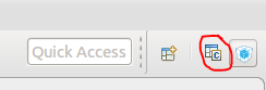
- Open the STM32CubeMX "perspective." To do this, look at the right side of the toolbar; all the way on the right hand side of the window. If you have used the STM32CubeMX perspective from the last blog post, click on the blue square with "MX" on it. Otherwise, click on the icon with a plus sign in the upper right and in the "Open Perspective" dialog box, select STM32CubeMX and click OK.
- In the STM32CubeMX perspective, click "New Project." (If you don't get the STM32CubeMX welcome screen, select New Project from the File menu inside STM32CubeMX.)
- STM32CubeMX will check for new files on ST's website. Be patient as the new files are downloaded.
- In the New Project dialog box, click on the Board Selector tab. (Note: current versions of STM32CubeMX use checkboxes, older versions used dropdown selections. In either case, the use should be straightforward.)
- In the "Type of Board" dropdown, select "Discovery."
- In the "MCU Series" dropdown, select "STM32F4."
- In the resulting boards list, double-click the STM32F429I-DISCO (or DISC1, depending on the board you have) board.
- If prompted to initialize all peripherals with their default mode, choose No.
- Give STM32CubeMX a few seconds to load the appropriate files and display the pinout of the STM32F429 chip on our dev board.
Let's take a moment to explore the UI here. There are four tabs along the top of the window content: Pinout & Configuration, Clock Configuration, Project Manager, and Tools.
In the Pinout & Configuration tab, we can assign pins to the various peripherals on the chip, and enter settings for those peripherals. This GUI can be a tremendous timesaver, as it ensures that one and only one function is assigned to each pin, it shows conflicts between pins, and it shows alternate pins for various peripheral functions. In the case of the discovery board, many of the pins are 'pinned' because the board is already hardwired to peripherals soldered to the dev board. If you were developing your own circuit, you could use this screen to play with the various options and find configurations that ensure all of your desired peripherals are available to you. In the left-hand pane, the chip's various peripherals are listed by category, each of which can be expanded. Each peripheral might have a yellow 'caution' icon or a red 'error' icon, indicating that either some functions of the peripheral are unavailable due to other selections, or that the peripheral can't be used, respectively. A peripheral listed in black is not configured or is disabled. A peripheral with a yellow bang has one or more features that conflict with existing pinout settings. That means that some of the features are available, but some aren't. A peripheral in red has all of its functions unavailable due to other pin assignment settings. Peripherals with a green checkmark are enabled and configured. Take a few minutes to explore this interface. This tab also allows you to configure the various software "middlewares" that you can select for your project. We'll explore these options (FATFS, FREERTOS, Graphics (STemWin or TouchGFX), LWIP, LIBJPEG, MBEDTLS, PDM2PCM, USB_DEVICE, and USB_HOST) in later installments of the series.
The Clock Configuration tab is, quite frankly, a marvel. If you haven't read the Reset and Clock Control (RCC) section of the Reference Manual, take a look at Figure 16 in the tome. It shows the clock tree of the STM32F4, which supplies no fewer than 16 clocks (!) to various parts of the chip. These clocks can be sourced by five clock sources (HSI, HSE, PLL, LSI RC, and LSE). There are twenty-six 32 bit registers that control these clocks. Each clock has its own range of allowable values and disallowed values. There's math and bit-shifting and division involved and it can all get quite complicated and messy to manually figure out clock settings. The Clock Configuration tab makes it easy to graphically adjust these settings to get the clock frequencies you desire.
The Project Manager tab controls your project name and code building options.
The Tools tab has some power draw simulations that you can play with. Maybe one day I'll explore this, but right now I have no intention of covering this in my tutorial series.
All of the settings on these tabs are automatically folded into the code generated by STM32CubeMX so that you don't have to worry about chip and peripheral initialization. It can be quite wonderful to have these chores done for you.
Configuring the Project
For our first project, I'm going to just tell you what settings to change. Later, we'll talk about them in more detail. In STM32CubeMX, do the following:
- On the Pinout & Configuration tab, expand the System Core section and click on GPIO.
- In the Configuration pane, click on PA0.
- In the PA0/WKUP Configuration pane that appears, note that the GPIO mode is limited; we can only select from the input I/O modes. This is because STM32CubeMX 'knows' that there's a button on this pin and won't allow us to configure the pin for output. Leave the GPIO selection at "External Event Mode with rising edge trigger detection" and the GPIO Pull-up/Pull-down mode to "No pull-up and no pull-down."
- Change the label to 'B1'.
- Click on PG13.
- Note the GPIO mode dropdown only allows you to select output I/O modes. Because, yeah, there's an LED connected to the pin.
- Leave the GPIO output level at "Low," the GPIO mode at "Output Push Pull," and the pull-up/pull-down at "No pull-up and no pull-down." Leave the output speed at "Low" and change the User Label to "LD3."
- n the Clock Configuration tab, ensure the PLL Source Mux is set to HSI. (It should already be set this way.) This causes the chip to use the high-speed internal oscillator as the main clock source.
Automatic Code Generation
Now we're going to tell STM32CubeMX to create a System Workbench project for us based on the settings we just configured. The only real changes we made were to the labels of the I/O pins, but for a complex project there are many, many settings that you can make in STM32CubeMX to configure and initialize peripherals, and these settings result in changes to the generated code. Let's generate the code.
- In the File menu in the STM32CubeMX tab (Not the file menu in the main Eclipse window), select Save Project.
- Create a folder on your machine in a convenient location and call it "STM32F429TutorialProjects" if you didn't in the previous tutorial.
- Inside that folder, create a folder named "Part5_GPIO_Polling"
- Click the Save button.
The *.ioc file that we just saved is an STM32CubeMX file. It has all the settings that are made in the various tabs of the GUI. If you'd care to examine it, it's a text file that you can open up and read in any text editor.
Now that we have our settings, we can generate our code:
- Click on the Project Manager tab.
- This tab is a mess of a UI, but we can work with it. In the section labeled "Code Generator" on the left, change the "Toolchain/IDE" selection to "SW4STM32."
- Click "Generate Code" in the upper right part of the screen, under the social media icons.
- If this is the first project you've created with STM32CubeMX, it will automatically download and install necessary files for the STM32F4 platform.
When the code is generated, you'll get a success dialog. Click the Open Project button. Then click OK on the "Successfully imported..." dialog.
In the Eclipse toolbar, choose the C/C++ perspective:
In the left-hand Project Explorer pane, click the triangle to the left of the Part5_GPIO_Polling folder to expand it. Expand the Src file and double-click main.c to open it in the text editor. There's a lot to talk about here, but we'll save that for later.
Writing the Code
So let's think about our code. We already know that we need a main loop, and in the main loop we're going to check to see if the button is pressed or not, and we're going to light the LED (or not). So the first thing we need to do is figure out which pins on the microcontroller are connected to the green LED and the user button. For that we use the schematic in the STM32F429 DISCOVERY user manual from ST's website (download document UM1670 on that page). This is a 36 page .pdf file that has, among other things, a schematic of the board. In section 1, "Features," the green LED is labeled LD3. Section 6.5 of the manual tells us that LD3 is connected to PG13. (That is, I/O port G, bit 13.) The B1 user button is connected to PA0 (port A, bit 0) as listed in section 6.6.
So: we need to determine if Port A, Bit 0 is high or low, and then set Port G, Bit 13 respectively.
Quiz: is Port A, Bit 0 logic high or logic low when the button is pressed? Go ahead, figure it out before reading ahead.
Page 33 of the .pdf file shows Figure 14, a schematic diagram of the peripherals on the board. The schematic shows that PA0 is connected to a 330 ohm resistor, the other end of which is tied to ground through a 220K resistor and that B1 is normally open. Therefore, when the button is not pressed, there is a logic low (ground voltage) on pin PA0. When B1 is pressed, that 330 ohm resistor is shorted to VDD, the logic high level. The 220K resistor ensures that there's no short circuit between VDD and ground when the button is pressed. Resistor R25 and capacitor C11 form a 'debounce' circuit to prevent PA0 from oscillating very rapidly several times as the physical contacts on the button are engaged or disengaged. This bouncing is simply an artifact of how physical contacts work on very small time scales such as the instruction clock of a microcontroller. The debounce circuit is not necessary but makes programming a lot easier.
So: PA0 is low (GND) when the button is not pushed, and high (VDD) when the button is pushed.
So that's that. What about the LED?
Quiz: Should we output a logic high or a logic low on Port G, Pin 13 to light the LED? You already have the .pdf open to the right diagram to figure it out, so go look before reading on.
Again in Figure 14, we can see that LD3 has the cathode connected to ground, and the anode connected to PG13 through a 510 ohm resistor. So: we'll need to output a logic high to light the LED.
Our code's main loop, therefore, should work like this:
IF PA0 == HIGH, set PG13 HIGH, ELSE set PG13 LOW.
Now: how do we do that?
This is where reading the documentation comes in. And for a chip like the STM32F4, it can be a lot of reading. The reading we need to do is in the reference manual for the STM32F4, document RM0090 on ST's page for the STM32F429ZI microcontroller. Download the manual and save it on your hard drive; you're going to need to refer to it. A lot. Chapter 8 of the Reference Manual is the one on GPIO. (GPIO is an acronym for 'general purpose input/output.') This chapter is 22 pages long, which makes it one of the shorter chapters in the manual.
You should really, really read this chapter. Really. I mean, yes, I'm going to tell you how to light the LED, but you really should read the manual so you understand it all.
Really.
Okay, with that out of the way, here's what we need to do: we need to read the input data register on Port A. We need to determine if Bit 0 is high or low. This is reasonably straightforward. In main(), write the following code inside the while(1) block, between the USER CODE BEGIN WHILE and the USER CODE END WHILE comments:
[cc lang = "c"]
x = HAL_GPIO_ReadPin(B1_GPIO_Port, B1_Pin);
HAL_GPIO_WritePin(LD3_GPIO_Port, LD3_Pin, x);
[/cc]
That's our main code loop right there!
Note that Eclipse is giving us red squigglies under the uses of our variable 'x' because this variable isn't declared in our code. At the top of the file, between the USER CODE BEGIN PV and the USER CODE END PV comments, delcare x as as type GPIO_PinState:
[cc lang="c"]
GPIO_PinState x;
[/cc]
Save the main.c file.
Building the Code
First, select the Console tab in the bottom pane. Then, from the Project menu, select Build All. You should see the output of the compiler and linker as your project is built. When the build is complete, you should see "Build Finished" and an elapsed time. If you get compiler or linker errors, read them carefully and go back and correct any mistakes that were made.
Programming the Microcontroller
Ensure the USB-Mini connector for the ST-Link debugger is connected to the machine on which Eclipse is running. (If you're running in a VM, ensure the USB device is connected to the VM.) In the bottom pane of the window, click on the Console tab so you can see a little of what's happening behind the scenes.
In Eclipse, from the Project menu, select "Build All" to build the project. (If you haven't done that already, that is.)
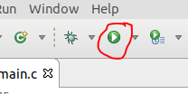
Once the code is built, click the green "Run" button in the toolbar:
When prompted, run the project as an "Ac6 STM32 C/C++ Application."
If prompted, in the "Complete board definition," select the SWD debug interface. (NOTE: This dialog can sometimes be behind the main Eclipse window. Check your taskbar to see if there's an extra window hiding back there.)
Eclipse will connect to the ST-Link debugger and flash your code into the STM32F429 microcontroller, and will run the program. The Console output can be a bit difficult to decipher, but in the bottom few lines of output you should see "Verified OK" and "Resetting Target." This tells you that GDB was able to verify that the code sent to the microcontroller was actually written to the microcontroller's flash memory, and that the microcontroller was reset, and thus is running our program.
Press the blue button. Note the green LED lights. Release the blue button. Note the green LED goes out.
For Extra Credit
Try editing the program so that the red LED (LD4) lights when the button is pressed instead of the green LED.
Conclusion
Well, that's about the simplest STM32 project I can think of. Two lines of code is all it took. Of course, we didn't cover why it works, or what's happening behind the scenes, but we were able to get a project up and running quickly, and hopefully the satisfaction of getting this simple program running will get you to come back for more!
Until then, happy blinky!
Im a ROTS Starter,
thank you for your work
Hello,
still following your blog. like it very much.
Brings me through these STM32 procedures.
I guess I know now why Arduino became so popular…
So much more simple and quick success.
But the STM32 has its specific advantages.
Please make your blog website responsive. I use a 24 inch monitor but your blog is a 1/3 display slim coloum….
Its bit tiring to read by scroling up amd down.
reload of captcha code does not work, its nice to reload if its hard to read
Thanks Oliver
Thank you for your work on this walk-through!
I noticed that your last entry was around Feb 2019, I hope you are well.
Thank you again
Jarrad