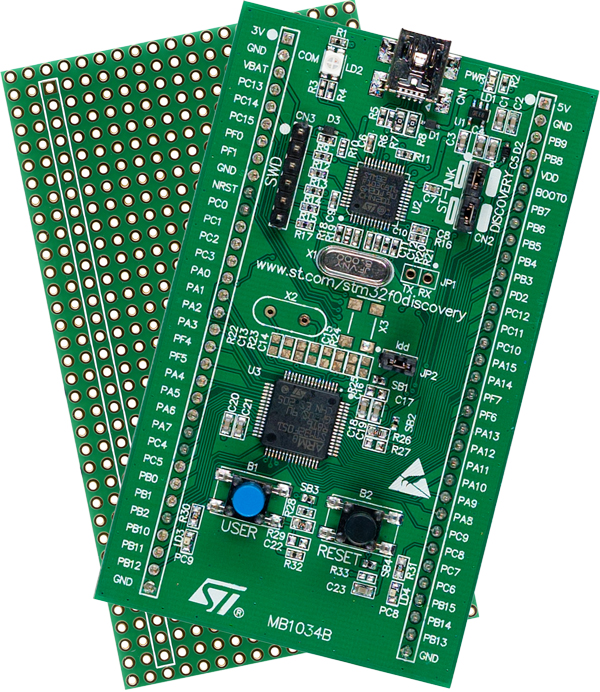
The STM32F0DISCOVERY board is a great platform for learning ARM microcontroller programming. For only $8 (Digikey, Mouser), you get a dev board with a STM32F051R8T6 microcontroller and an onboard ST-LINK programmer/debugger. Unlike dev boards from other manufacturers, the programmer is designed so that it can be used to program the onboard microcontroller, or it can be used as a standalone programmer. The board can be powered via USB and contains two user LEDs and one user button. All of the microcontroller's I/O pins are brought out to header pins on the dev board. The header pins are single-row pins, so the board can be put into a breadboard. As it ships, the microcontroller runs at 48MHz off an internal RC oscillator, but there are unpopulated pads on the PCB where you can add your own crystals for both the high speed clock and a 32.768 kHz crystal for the real-time clock/calendar.
Allow me to plagiarize the features list for the STM32F051R8 processor from ST's website:
- Core: ARM 32-bit Cortex™-M0 CPU,frequency up to 48 MHz
- Memories
- 16 to 64 Kbytes of Flash memory
- 8 Kbytes of SRAM with HW parity checking
- CRC calculation unit
- Reset and power management
- Voltage range: 2.0 V to 3.6 V
- Power-on/Power down reset (POR/PDR)
- Programmable voltage detector (PVD)
- Low power Sleep, Stop, and Standby modes
- VBAT supply for RTC and backup registers
- Clock management
- 4 to 32 MHz crystal oscillator
- 32 kHz oscillator for RTC with calibration
- Internal 8 MHz RC with x6 PLL option
- Internal 40 kHz RC oscillator
- Up to 55 fast I/Os
- All mappable on external interrupt vectors
- Up to 36 I/Os with 5 V tolerant capability
- 5-channel DMA controller
- 1 x 12-bit, 1.0 us ADC (up to 16 channels)
- Conversion range: 0 to 3.6V
- Separate analog supply from 2.4 up to 3.6 V
- One 12-bit D/A converter
- Two fast low-power analog comparators with programmable input and output
- Up to 18 capacitive sensing channels supporting touchkey, linear and rotary touch sensors
- Up to 11 timers
- One 16-bit 7-channel advanced-control timer for 6 channels PWM output, with deadtime generation and emergency stop
- One 32-bit and one 16-bit timer, with up to 4 IC/OC, usable for IR control decoding
- One 16-bit timer, with 2 IC/OC, 1 OCN, deadtime generation and emergency stop
- Two 16-bit timers, each with IC/OC and OCN, deadtime generation, emergency stop and modulator gate for IR control
- One 16-bit timer with 1 IC/OC
- Independent and system watchdog timers
- SysTick timer: 24-bit downcounter
- One 16-bit basic timer to drive the DAC
- Calendar RTC with alarm and periodic wakeup from Stop/Standby
- Communication interfaces
- Up to two I2C interfaces; one supporting Fast Mode Plus (1 Mbit/s) with 20 mA current sink, SMBus/PMBus, and wakeup from STOP
- Up to two USARTs supporting master synchronous SPI and modem control; one with ISO7816 interface, LIN, IrDA capability auto baud rate detection and wakeup feature
- Up to two SPIs (18 Mbit/s) with 4 to 16 programmable bit frame, 1 with I2S interface multiplexed
- HDMI CEC interface, wakeup on header reception
- Serial wire debug (SWD)
- 96-bit unique ID
For only $8, this is an incredible value. Once you've designed your product on the DISCOVERY board and are ready to build a production PCB, the STM32F051R8 microcontroller costs $3.77 in single unit quantities from Digikey and Mouser.
Let's create our first project for the STM32F0DISCOVERY board. We're going to use the files that ST ships with the STM32F0DISCOVERY firmware and the Standard Peripheral Library firmware to build a the demo project that ships preinstalled on the STM32F0DISCOVERY board. At the end of this tutorial, we'll have compiled code that we can upload to the STM32F0DISCOVERY board with the ST-LINK utility. In later tutorials, we'll get this project ready for cloning, and we'll create a custom demo app for our board.
NOTE: This is not a "do this, do that, you're done" tutorial. This is essentially a journal of the steps I went through when I first installed and configured these tools on my machine, along with the troubleshooting steps I had to go through to solve the problems I encountered. (With the dead ends removed.) I encourage you to follow along and make the same mistakes I made as you set up your environment. The process will be a good learning experience, and may provide you with the tools and knowledge you need to solve other problems you may run into in your future programming endeavors for the ARM platform. I learned A LOT by writing this blog post, exploring the build process to get it right, and proofreading my writing for errors. I hope you get as much out of this as I did.
Step 1: Create a Workspace
If you haven't yet done so, install the ARM GCC compiler and the Eclipse IDE by following the instructions in a previous blog post, Getting Started with the ARM GCC Compiler on Windows, Part 1.
Open the Eclipse IDE. If prompted, select a suitable Workspace. As I discussed in my first post on the topic, I created a separate folder for each target platform on which I'll be developing, and I created a symbolic link off the root of my C:\ drive to point to the location in my My Documents folder that will hold my workspace. As far as Eclipse is concerned, my workspace is C:\Arm_Development\STM32F0. If you'll notice, Eclipse added a folder name ".metadata" to the root folder of your workspace as soon as you opened your workspace location. Eclipse uses this folder to keep track of workspace settings. It's best not to touch this folder.
Step 2: Install Required Libraries
It's extraordinarily unlikely that you'll be writing all of the code for your project from scratch. The major microcontroller vendors all provide libraries in the form of object (.o) files and source code, and other code samples, to help you get up to speed quickly on their products. Since we're all good developers here, we know not to re-invent the wheel. Let's download and install the libraries that ST provides for STM32F0 development. Go to http://www.st.com and search for "STM32F0DISCOVERY." I expect that ST's website will change by the time you read this, but as I write this the product page for the eval board is here.
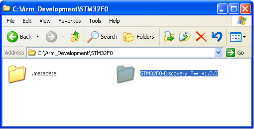
Click on the Design Support tab and scroll down to the Firmware section. Download the "STM32F0 Discovery kit firmware package, including 21 examples and preconfigured projects for 4 different IDEs" package. Extract the contents of this .zip file to your workspace:
Open the firmware folder and you'll see a release notes .html file, a license agreement, and a Project, a Libraries, and a Utilities folder. Be sure that you read and agree to the license agreement before developing with these resources.
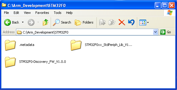
In the Libraries folder, you'll find two folders: CMSIS and STM32F0xx_StdPeriph_Driver. Unfortunately, these libraries are already out of date. The STM32F0xx Standard Peripherals Library Drivers that ships with the STM32F0DISCOVERY kit firmware is versioned 1.0.0 and is dated March 23, 2012. These are not the same files that ship in the "STM32F0xx Standard Peripherals Library" (note the absence of the word "Drivers"), which is also version 1.0.0 but is dated May 18,2012. I don't know what the story is here, but my interpretation is that someone at ST screwed up. I did a WinDiff of these two libraries, and while the vast majority of the differences between the libraries are solely in the comments, there are a few code changes (particularly in usart.c). A more important difference between these two packages is that the standalone STM32F0xx Standard Peripherals Library includes documentation (in the form of a .chm file), whereas the version that ships with the STM32F0DISCOVERY firmware package has no documentation. My recommendation, therefore, is to download the standalone STM32F0xx Standard Peripherals Library. You can find this on ST's website by searching on a particular STM32F0 part (such as the STM32F051R8T6), clicking on the Design Support tab, scrolling down to the Firmware section, and downloading the most recent STM32F0xx Standard Peripherals Library. Extract the contents of the .zip file to the root of your workspace.
Step 3: Download the Clock Configuration Tool
Browse the Peripheral Library and look in the Project\STM32F0xx_StdPeriph_Templates folder. Open the system_stm32f0xx.c file in your favorite text editor. Note that the comments in the header of this file indicate that it was generated by "the clock configuration tool." This file will be a core part of any project you create for the STM32F0 processors. This file sets the SYSCLK, HCLK, AHB and APB prescalers, the clock PLL, the flash latency, and the prefetch buffer for the chip. The file, as it ships from ST, configures the chip to run at 48MHz from the High Speed Internal (HSI) oscillator. If you ever want to use an external crystal as the clock source for your project, or use a SYSCLK frequency other than 48MHz, you'll need to edit this file.
The clock configuration tool, unfortunately, doesn't ship with the Standard Peripherals Library. To find it, go to http://www.st.com and click on the Search tab. Search for a suitable STM32F0 part, such as the STM32F051R8T6 that ships on the STM32F0DISCOVERY board. On the product page, click on the Design support tab. Scroll down to the "Configuration Utilities" section and grab the Clock Configuration Tool. The download is a .zip file that contains an Excel spreadsheet. Extract to a convenient location on your hard drive. (Sadly, non-Microsoft Office users appear to be left out to dry here by ST.)
While you're on the product page, download AN4055 as well. This is the documentation for the clock configuration tool. The clock configuration tool is an interesting beast; rather than explain it here in this blog post I think it's best that I encourage you to read the app note. Of course, you should be familiar with the clock systems of the STM32F0 as well. This information is in Chapter 7 of the STM32F05xxx Reference Manual, which you should also download along with the datasheet for the STM32F051R8.
Step 4: Create a Template Project Structure
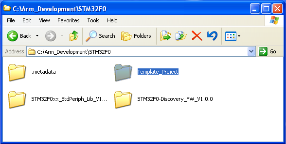
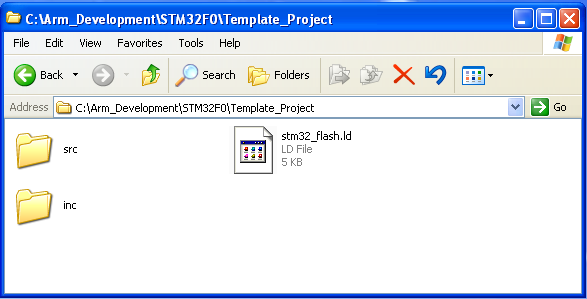
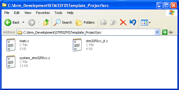
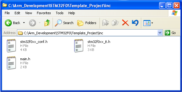
The easiest way to get up and running with a project of your own is to start with someone else's work and build upon it. Let's create a project, compile it, and test it, then use it as our baseline for future projects. In your workspace, create a folder named Template_Project. In that folder, create one folder named src and another named inc. Into the src folder, copy main.c, stm32f0xx_it.c, and system_stm32f0xx.c from the \STM32F0-Discovery_FW_V1.0.0\Project\Demonstration folder. (Note: You should copy these files, not move them! Instead of left-mouse-button dragging them from one folder to another, either use the copy/paste commands, or right-mouse-button drag them and select "Copy" when you release the mouse button.) Into the inc folder, copystm32f0xx_conf.h, stm32f0xx_it.h, and main.h from the \STM32F0-Discovery_FW_V1.0.0\Project\Demonstration folder. These files form the bulk of our project code.
Having all the code is not sufficient for building an embedded application. While our source code will compile, linking it is a bit more difficult with embedded systems than it is with a desktop computer. Microcontrollers have a very limited amount of ROM and RAM. In addition, peripherals are mapped into the same address space as memory. Certain pieces of code, such as the reset vector and interrupt vectors, need to be placed at predefined locations in memory. In order to ensure that all the parts of our compiled project land in the correct spots in the memory map, the linker needs a resource, called a linker script, that tells it how to arrange the memory map. Open \STM32F0\STM32F0xx_StdPeriph_Lib_V1.0.0\Project\STM32F0xx_StdPeriph_Templates\TrueSTUDIO\Project and copy stm32_flash.ld to the root of the project template folder. When you're done, your file and folder structure should look like this:
- Template_Project
- stm32_flash.ld (the linker script)
- src
- main.c (the main code for the project)
- stm32f0xx_it.c (code for interrupt handlers)
- system_stm32f0xx.c (the clock configuration tool output)
- inc
- main.h
- stm32f0xx_conf.h (uncomment lines here to include various peripheral libraries)
- stm32f0xx_it.h
Step 5: Configure the GCC Toolchain in Eclipse and Build the Project
Now that we have our project files, we can create a project in Eclipse and configure Eclipse to build our project with the cross compiler tools that we've installed. Eclipse will store our settings in the .project file in the project's folder, so that we can make copies of our template project (after it's configured, of course) and the configuration settings will be copied to our new project. Getting these settings correct in our template project is the hard part. Once that's done, we can copy-and-paste to our heart's content and know that any future projects created by copying our template project will have the correct configuration settings.
A word of warning: I wrote this as a learning exercise, not as a solution on a silver platter. We're going to encounter a number of errors on our way to getting our project to build, and we'll fix each one as we see it. This isn't the fastest way for you to get up and running, but hopefully it'll teach you how to solve some of these problems when you encounter them later, when you're working on your own without a tutorial in front of you.
If you're not running Eclipse, go ahead and fire it up now. If you didn't open your STM32F0 folder as your workspace, go to File -> Switch Workspace and open your STM32F0 development workspace.
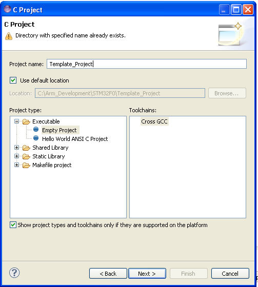
From the File menu, choose New -> Project.... You'll be prompted to select a New Project wizard to use. Expand the C/C++ node and choose "C Project" and click Next. For the project name, enter "Template_Project" and ensure the "use default location" checkbox is checked. You should see a warning pop up at the top of the window, warning you that a directory with the specified name already exists. In the toolchains list on the right hand side of the window, select "Cross GCC." Click Next.
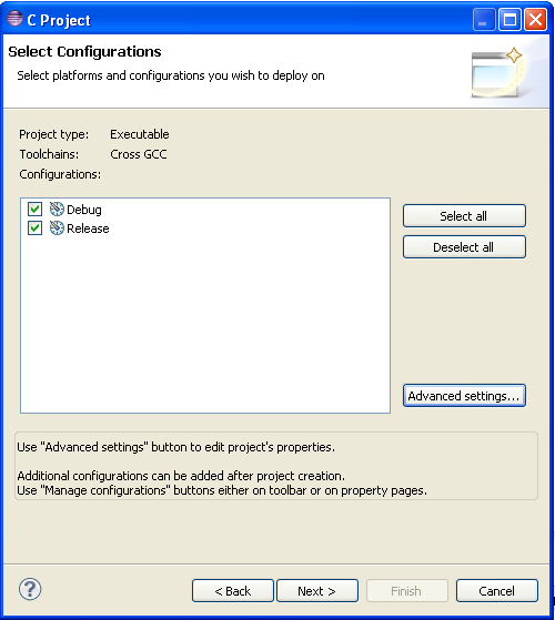
The next page of the wizard allows you to select configurations. By default we're given a Debug and a Release configuration. That should suffice for most of us for a while; you can add configurations to your projects later if you need to, so we'll leave things as they are. Ignore the Advanced settings button. We'll configure advanced settings in a moment. Click Next.
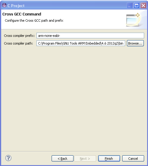
In the third page of the wizard, Eclipse is asking you for the cross compiler prefix and the cross compiler path. The prefix is 'arm-none-eabi-' (include the trailing dash), and the path is the 'bin' folder in the location into which you installed GCC.
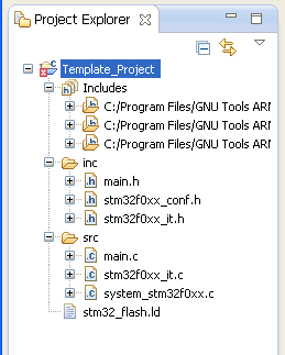
When you click Finish, Eclipse will create a new project for you. Eclipse should detect all of the files we just populated into our Template_Project folder and you should see them in the Project Explorer on the left side of your screen:
As an exercise, let's attempt to build our project. Ensure that the Template_Project folder is selected in Project Explorer, and from the Project menu, choose "Build Project." (You may have to first uncheck the "Build Automatically" option in this menu.) Most likely, your project didn't build. Check the Problems tab for details:
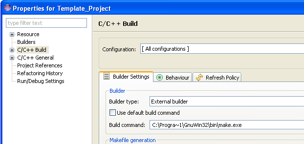
Eclipse has given us a pretty clear error message here. While we did install the GNU MAKE utility in the part I of this tutorial, Eclipse doesn't know where on our hard drive the make program is. There are a few ways we could solve this. We could change the Windows system or user path to include the path to MAKE. We could copy MAKE into the same folder as GCC (which we put into system path when we installed GCC) as Dr. Al-Hertani does in his tutorials. My solution is to explicitly tell Eclipse where MAKE is. From the Project menu, select Properties. In the treeview on the left, select "C/C++ Build." In the Configuration dropdown, select "[All Configurations]." On the Builder Settings tab, uncheck the "Use default build command" checkbox. Let's change the build command from "make" to the full path to the MAKE tool on your hard drive. Now, remember what I said in my first tutorial about command line tools not playing well with paths that include spaces? Well, MAKE is one such tool, and it's in the "Program Files" folder by default. If we simply enter the full path to make.exe, it won't work. (Even if we enclose the path in quotations marks. I tested it.)
So we're going to use something of a hack. It's a perfectly legitimate thing to do, but Windows purists might be a bit put off by this. Every long filename in Windows also has a short filename that the operating system maintains without telling us. Unless you did something truly bizarre on your computer since installing your operating system, the short filename for "c:\Program Files" on your system is "c:\Progra~1". So enter the path to MAKE as "C:\PROGRA~1\GnuWin32\bin\make.exe." Be sure to select "[All Configurations]" when you do:
(Note that Windows filenames are not case-sensitive, unlike UNIX/Linux environments.)
Click OK and attempt to build the project again. (Highlight the project in the Project Explorer, from the Project menu, select Build.) Note that this time we get a different error:
Eclipse is telling us that the compiler can't find our main.h file. The best place to put header (.h) files can be debated, but I prefer to maintain them in an \inc folder separate from the \src folder. The reason that GCC can't find main.h is that we didn't tell it where we put our header files.
Now, there are a couple of ways we can fix this in Eclipse, and the two methods have different results. In my first attempt at solving this, I went to Project, Settings, selected C/C++ Build, settings, the Tool Settings tab, went to the Cross GCC Compiler node, then the Includes node, and added my include paths there. This did, in fact, allow the project to build. However, the Eclipse IDE still flagged lines in my source code with errors because, while the build process could find my includes, the Eclipse environment could not.
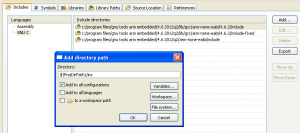
Instead, let's add the include path to a different location. From the Project menu, select Properties. In the treeview in the left pane, expand C/C++ General, and highlight the Paths and Symbols node. Ensure the Includes tab is selected. Click on "GNU C" in the Languages list on the left. Click the Add button, and type the path:
${ProjDirPath}/inc
Be sure to check the box "Add to all configurations" (click for larger version):
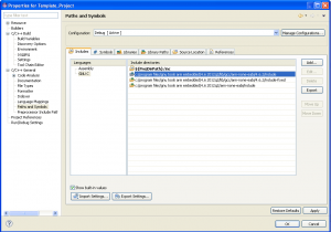
It'll look like this after you click OK (click for larger image):
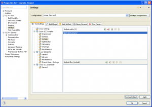
Now, if you look at the Includes path for the Cross GCC Compiler, you'll see that the include path we created is added to this list as well (again, click for larger image):
Click OK and attempt to build the project. Notice that we get a new error:
This time, the compiler can't find stm32f0xx.h. But this isn't a file in our project! What's going on here? Again, Eclipse tells us what we need to know. In line 33 of main.h, there's an #include directive for stm32f0xx.h. This header file is part of the Standard Peripheral Library that we downloaded earlier. Let's add the path to the peripheral library to the list of include paths. The path you want to enter is:
${ProjDirPath}/../STM32F0xx_StdPeriph_Lib_V1.0.0/Libraries/CMSIS/Device/ST/STM32F0xx/Include
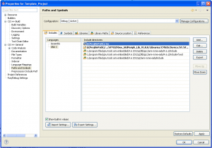
Once again, go to Project -> Properties -> C/C++ General -> Paths and Symbols -> Includes tab -> select GNU C and click Add. Again, ensure that you add this path to all build configurations. Your project settings should look like this (again, click for a larger version):
OK, so let's attempt to build the project again: click OK and from the Project menu select Build Project. Rats... we get another build error:
The stm32f0xx.h file is referencing a header file core_cm0.h that the toolchain can't find. We know that the stm32f0xx.h file is part of the Standard Peripherals Library, so it's a good bet that the dependency files are in the library as well. (Once we're done configuring our build environment, I'll go back and explain what each of these header files is used for. That's a topic for a later blog post.)
The new include path that we need to add to our build environment is:
${ProjDirPath}/../STM32F0xx_StdPeriph_Lib_V1.0.0/Libraries/CMSIS/Include
Add the new path, again ensuring that it's added to all configurations. OK; let's build this project (or at least try to) again. Argh! We get yet another .h file that the build environment can't locate:
The file in question is the stm32f0_discovery header file, located in the STM32F0-Discovery_FW_V1.0.0 folder, is a header file that defines some items particular to the STM32F0DISCOVERY board, such as the user LEDs and the user button, along with the GPIO pins to which these parts are connected. Add the following path to your project's properties (again, ensure it's added to all configurations):
${ProjDirPath}/../STM32F0-Discovery_FW_V1.0.0/Utilities/STM32F0-Discovery
Now when we build, we get a slew of odd errors:
What's happening here is that the compiler is unable to resolve the symbols HCLK_Frequency or RCC_ClocksTypeDef. These symbols are all defined in the stm32f0xx_rcc.h file. RCC stands for Reset and Clock Control, and is described in chapter 7 of the microcontroller's reference manual.
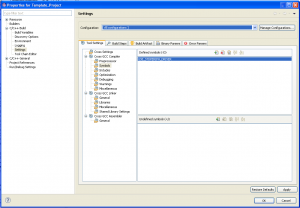
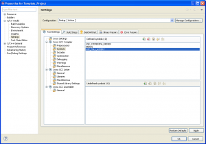
The RCC constants are defined in stm32f0xx_rcc.h, which is #included by stm32f0xx.h if the USE_STDPERIPH_DRIVER symbol is defined (line 3193). (The file stm32f0xx.h is #included by main.h in line 33, which is #included in main.c on line 29.) Typically, these symbols are created with #define preprocessor directives in .h or .c files. However, they can also be specified in command-line arguments to the GCC compiler. To get our project to build properly, we need to define the USE_STDPERIPH_DRIVER symbol in all of the files we build. (Well, at least for all of the files in the standard peripheral library that we build.) We can do this in the Eclipse GUI. Go to Project... Properties. In the settings dialog, expand C/C++ Build, and under that select the Settings node. Go to the Tool Settings tab, and in the left pane of that tab, expand the Cross GCC Compiler section and click on the Symbols node. In the Configuration dropdown, ensure that "[All Configurations]" is selected. In the Defined symbols window, click the plus icon to add a symbol. Add the symbol name USE_STDPERIPH_DRIVER (click for larger version):
OK, you know the drill: let's build again and see what's broken this time:
Although we included stm32f0xx_conf.h in our project, a file that it references (stm32f0xx_cec.h) can't be found. We need to add another include path, this time to the Peripheral Library. Add the following path:
${ProjDirPath}/../STM32F0xx_StdPeriph_Lib_V1.0.0/Libraries/STM32F0xx_StdPeriph_Driver/inc
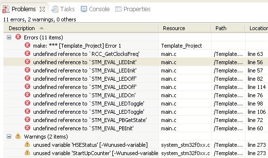
(Remember, that's Project -> Properties -> C/C++ General -> Paths and Symbols -> Includes -> GNU C. Remember to check "Add to all configurations.") Once you add this path and try to build again, you'll notice that we get different kinds of errors:
Now, this may be a little confusing at first... we already told the build process the location of the header files in which these symbols are defined... so why can't the compiler find them?
The answer is that the compiler can and did find them. It's the linker that's having problems. Click on the Console tab and review the output from the build process. You'll see that make.exe was invoked, and it in turn invoked the GCC compiler to build main.c (line 3 below), stm32f0xx_it.c (line 8 below), and system_stm32f0xx.c (line 13 below), the three .c files in our project. Each of these finished building (lines 6, 11, and 19 below).
[cc]19:13:31 **** Incremental Build of configuration Debug for project Template_Project ****
"C:\\PROGRA~1\\GnuWin32\\bin\\make.exe" all
'Building file: ../src/main.c'
'Invoking: Cross GCC Compiler'
arm-none-eabi-gcc -DUSE_STDPERIPH_DRIVER -I"C:/ARM_Development/STM32F0/Template_Project/inc" -I"C:/ARM_Development/STM32F0/Template_Project/../STM32F0xx_StdPeriph_Lib_V1.0.0/Libraries/CMSIS/Device/ST/STM32F0xx/Include" -I"C:/ARM_Development/STM32F0/Template_Project/../STM32F0xx_StdPeriph_Lib_V1.0.0/Libraries/CMSIS/Include" -I"C:/ARM_Development/STM32F0/Template_Project/../STM32F0-Discovery_FW_V1.0.0/Utilities/STM32F0-Discovery" -I"C:/ARM_Development/STM32F0/Template_Project/../STM32F0xx_StdPeriph_Lib_V1.0.0/Libraries/STM32F0xx_StdPeriph_Driver/inc" -O0 -g3 -Wall -c -fmessage-length=0 -MMD -MP -MF"src/main.d" -MT"src/main.d" -o "src/main.o" "../src/main.c"
'Finished building: ../src/main.c'
' '
'Building file: ../src/stm32f0xx_it.c'
'Invoking: Cross GCC Compiler'
arm-none-eabi-gcc -DUSE_STDPERIPH_DRIVER -I"C:/ARM_Development/STM32F0/Template_Project/inc" -I"C:/ARM_Development/STM32F0/Template_Project/../STM32F0xx_StdPeriph_Lib_V1.0.0/Libraries/CMSIS/Device/ST/STM32F0xx/Include" -I"C:/ARM_Development/STM32F0/Template_Project/../STM32F0xx_StdPeriph_Lib_V1.0.0/Libraries/CMSIS/Include" -I"C:/ARM_Development/STM32F0/Template_Project/../STM32F0-Discovery_FW_V1.0.0/Utilities/STM32F0-Discovery" -I"C:/ARM_Development/STM32F0/Template_Project/../STM32F0xx_StdPeriph_Lib_V1.0.0/Libraries/STM32F0xx_StdPeriph_Driver/inc" -O0 -g3 -Wall -c -fmessage-length=0 -MMD -MP -MF"src/stm32f0xx_it.d" -MT"src/stm32f0xx_it.d" -o "src/stm32f0xx_it.o" "../src/stm32f0xx_it.c"
'Finished building: ../src/stm32f0xx_it.c'
' '
'Building file: ../src/system_stm32f0xx.c'
'Invoking: Cross GCC Compiler'
arm-none-eabi-gcc -DUSE_STDPERIPH_DRIVER -I"C:/ARM_Development/STM32F0/Template_Project/inc" -I"C:/ARM_Development/STM32F0/Template_Project/../STM32F0xx_StdPeriph_Lib_V1.0.0/Libraries/CMSIS/Device/ST/STM32F0xx/Include" -I"C:/ARM_Development/STM32F0/Template_Project/../STM32F0xx_StdPeriph_Lib_V1.0.0/Libraries/CMSIS/Include" -I"C:/ARM_Development/STM32F0/Template_Project/../STM32F0-Discovery_FW_V1.0.0/Utilities/STM32F0-Discovery" -I"C:/ARM_Development/STM32F0/Template_Project/../STM32F0xx_StdPeriph_Lib_V1.0.0/Libraries/STM32F0xx_StdPeriph_Driver/inc" -O0 -g3 -Wall -c -fmessage-length=0 -MMD -MP -MF"src/system_stm32f0xx.d" -MT"src/system_stm32f0xx.d" -o "src/system_stm32f0xx.o" "../src/system_stm32f0xx.c"
../src/system_stm32f0xx.c: In function 'SetSysClock':
../src/system_stm32f0xx.c:273:37: warning: unused variable 'HSEStatus' [-Wunused-variable]
../src/system_stm32f0xx.c:273:17: warning: unused variable 'StartUpCounter' [-Wunused-variable]
'Finished building: ../src/system_stm32f0xx.c'
' '
'Building target: Template_Project'
'Invoking: Cross GCC Linker'
arm-none-eabi-gcc -o "Template_Project" ./src/main.o ./src/stm32f0xx_it.o ./src/system_stm32f0xx.o
c:/program files/gnu tools arm embedded/4.6 2012q2/bin/../lib/gcc/arm-none-eabi/4.6.2/../../../../arm-none-eabi/lib\libc.a(lib_a-exit.o): In function `exit':
exit.c:(.text.exit+0x2c): undefined reference to `_exit'
./src/main.o: In function `main':
C:\ARM_Development\STM32F0\Template_Project\Debug/../src/main.c:55: undefined reference to `STM_EVAL_LEDInit'
C:\ARM_Development\STM32F0\Template_Project\Debug/../src/main.c:56: undefined reference to `STM_EVAL_LEDInit'
C:\ARM_Development\STM32F0\Template_Project\Debug/../src/main.c:59: undefined reference to `STM_EVAL_PBInit'
C:\ARM_Development\STM32F0\Template_Project\Debug/../src/main.c:62: undefined reference to `RCC_GetClocksFreq'
C:\ARM_Development\STM32F0\Template_Project\Debug/../src/main.c:71: undefined reference to `STM_EVAL_PBGetState'
C:\ARM_Development\STM32F0\Template_Project\Debug/../src/main.c:75: undefined reference to `STM_EVAL_LEDOn'
C:\ARM_Development\STM32F0\Template_Project\Debug/../src/main.c:81: undefined reference to `STM_EVAL_LEDOff'
C:\ARM_Development\STM32F0\Template_Project\Debug/../src/main.c:97: undefined reference to `STM_EVAL_LEDToggle'
C:\ARM_Development\STM32F0\Template_Project\Debug/../src/main.c:105: undefined reference to `STM_EVAL_LEDToggle'
C:\ARM_Development\STM32F0\Template_Project\Debug/../src/main.c:113: undefined reference to `STM_EVAL_LEDOff'
collect2: ld returned 1 exit status
make: *** [Template_Project] Error 1
19:13:33 Build Finished (took 2s.143ms)
[/cc]
After the three .c files are compiled, make invokes the linker (line 22). And the errors come from the linker. This is progress for us! Our files compiled! (Stop and do the Happy Dance. Whenever your code actually compiles, treat it as the victory that it is. If you don't know what I'm talking about, you haven't yet experienced the Pit of Despair that is embedded programming. You'll eventually learn to celebrate these small victories as they come.)
Time for a review: the compiler's job is to compile each source file (.c) into an object library (.o). The linker's job is to take those object libraries and, well, link them together into a final binary. The linker is telling us that it can't find an .o file that defines the symbols STM_EVAL_LEDInit, STM_EVAL_PBInit, etc. If you look at the output, you'll see that we have two prefixes for all of these symbols. The STM_EVAL_ symbols are defined in the stm32f0_discovery.h and stm32f0_discovery.c files. The RCC_ symbol is defined by the Peripheral Library's RCC.h and RCC.c files.
ST has provided the peripheral libraries in the form of source code that we want to include in our project. If we want to use these libraries, we'll have to compile them ourselves. Now, we could compile them all in a separate project (or even independently from the command line) and link to the object files in our template project. A better idea is to include all of the library files we want to reference in our project. This will allow us to change compiler settings and have the new settings cause the libraries to be rebuilt with our settings. There are two ways of doing this. We could create a new folder in the filesystem, in our project folder, and copy the library source code to that location. Alternately, we can link to the source files in an existing location on our hard drive. If we were going to edit the library files for each project, it would probably make sense to make a separate copy of the source files for each project. Since we're unlikely to ever edit the library files that ST provides for us, let's save a little disk space and link to the existing location.
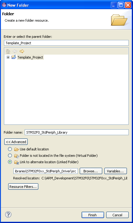
Right-clik on the root Template_Project folder in the Project Explorer and select New -> Folder. In the New Folder dialog, click the Advanced button. In the newly exposed controls, click the "Link to alternate location (linked folder)" radio button. Enter the following path:
WORKSPACE_LOC\STM32F0xx_StdPeriph_Lib_V1.0.0\Libraries\STM32F0xx_StdPeriph_Driver\src
In the "Folder name" textbox, enter "STM32F0_StdPeriph_Library." (Note: I wanted to specify this path relative to PROJECT_LOC, but the Eclipse IDE was unable to resolve the '..' path relative to the project folder, so I ultimately specified this path relative to the workspace instead.)
In the Project Explorer, expand the new STM32F0_StdPeriph_Library folder to see the source code files in there:
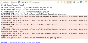
Now when we build, the compiler will busily compile all of the files we just added to our project. You can click on the Console tab to watch the progress. This time, the compiler stopped when compiling stm32f0xx_pwr.c with the following errors (click to enlarge):
Uh oh. What does that mean? This error came from the assembler, for crying out loud! We're not even using the assembler, right?
Well, let's investigate. Open stm32f0_pwr.c in the editor and search for 'wfi' and 'wfe.' We see calls to __WFI() in the .c file but this function isn't defined in this file. Put your cursor on a call to __WFI() in the file and right-click. Select "Open Declaration" from the context menu to have Eclipse take you to the declaration of this function. The function is defined in core_cmInstr.h and is coded with inline assembler. So we are, in fact, using the assembler here! Somehow the assembler knows that the wfi and wfe instructions are not supported on the processor for which we're building.
But how does the assembler know our target processor?
The assembler was called by the compiler, remember. So the compiler must have told the assembler (via command line arguments) which processor is being targeted.
This brings up the question: how does the compiler know which processor we're targeting? Well... remember when we installed GCC in my previous blog post and I suggested that the readme file has some good information in it? As it turns out, the readme tells us which flags to pass to the compiler for each processor architecture. Per that file, we should be using the command line arguments:
-mthumb -mcpu=cortex-m0
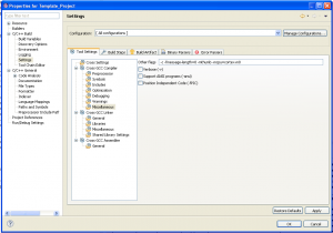
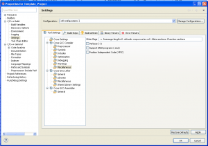
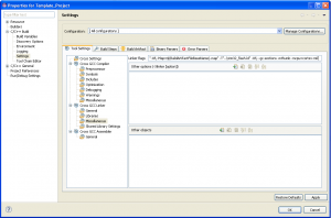
Let's go back to our project's properties dialog. In the tree in the left pane, go to C/C++ Build, then Settings. On the Tool Settings tab, click on Cross GCC Compiler, Miscellaneous. Ensure "[All Configurations]" is selected in the dropdown. In the "other flags" textbox, enter our new flags and click OK (click for full size):
Now, we've already compiled a bunch of our .c files into .o files with the old compiler flags. As it turns out, the compiler was compiling to the ARM instruction set, which the Cortex-M0 core doesn't support. We'll have to recompile all those files with the new settings that cause the compiler to compile to the Thumb instruction set. Thankfully, though the make utility is smart enough to not recompile any files that haven't changed since the last time they were compiled (i.e. incremental build), it is also smart enough to figure out that we're compiling with different command line arguments, and to recompile all of our code. We can build the project and all of our source files will be recompiled. And... lo and behold, stm32f0_pwr.c compiles this time!
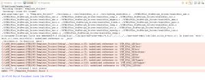
In fact, all of our files compiled. (Remember: Happy Dance!) The linker, however, had another problem, this time finding some symbols:
These symbols are used in main.c, which we copied from the STM32F0Discovery demo project. It looks like we're missing an .o file that has these symbols, which means we're missing a .c file that defines these symbols.
We need to add stm32f0_discovery.c to our project. This file is part of the demonstration program that ships preinstalled on the STM32F0DISCOVERY board. Again, we're faced with the choice of adding a linked folder to our project, or adding a physical folder. Using the same logic as last time, since we're unlikely to edit this file, a linked folder would be appropriate. For reasons that I'll explain later, I decided to add a new (physical) folder to the project and copy the files I needed to that location. From the File menu, select New-> Folder. Name the new folder STM32F0_DISCOVERY.
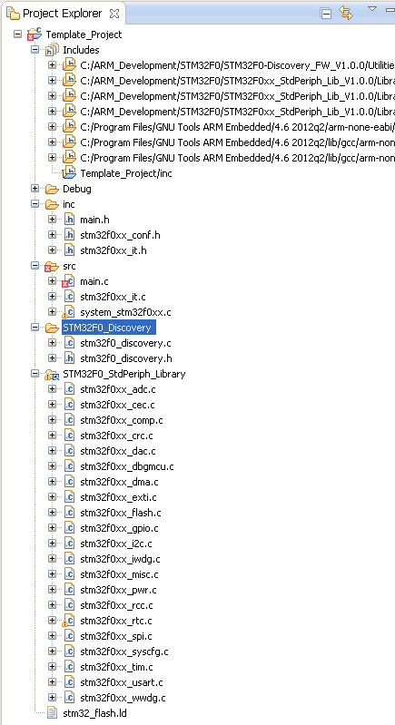
In the filesystem, copy the two files in C:\ARM_Development\STM32F0\STM32F0-Discovery_FW_V1.0.0\Utilities\STM32F0-Discovery to C:\ARM_Development\STM32F0\Template_Project\STM32F0_Discovery. In Eclipse, highlight the new folder in the Project Explorer and press F5 to get the IDE to 'see' the new files you placed there. Your project tree should look like this:
And build yet again.
Now we get a new linker error that we have an undefined reference to the symbol '_exit:'
Now, if you'll search our source code for the function _exit, you won't find any hits. (Go ahead. Try it. Really. From the Search menu, select Search.) Nowhere, in any of our source code, do we call a function _exit(). Yet the linker insists that it needs that function before it can link our project.
More curious, if we look at the console output, we find that the static library "libc.a" is what's attempting to reference _exit(). But nowhere in our project did we include a reference to this library!
So what's going on here? Well, it's kind of a long story. You see, most C compilers ship with a C standard library, which contains many macros, type definitions, and functions (like strcpy() and printf() and malloc()) that we're all accustomed to using in desktop environment C language programming. Header files such as stdio.h and math.h come from the C standard library. There are a couple of issues providing the C standard library for an embedded environment. The first is that many of the functions are large, in terms of either code or RAM space needed. The second, more complex issue is that the C standard library is intended to be an interface between the programmer and the operating system. In an embedded environment, many times there simply is no operating system. Take, for example, the C standard library function fopen(). This function is used to open a file. Functions such as fopen() lose their meaning when there's no filesystem attached to the computer on which code is running. Furthermore, in an embedded environment, the filesystem may reside on an MMC card, a USB thumb drive, an EEPROM, or may even be emulated over a link such as a serial port.
Clearly, there are significant challenges in porting the C standard library to an embedded system. To answer these challenges, newlib was created. Newlib is a simple ANSI C library, math library, and collection of board support packages for embedded systems. You can find out more at the newlib home page, maintained by Redhat.
The newlib library can't do everything. The library relies on a small set of host-dependent system calls. In order for newlib to run, these system calls must be available to the library. Thankfully, newlib has documented a minimum set of required syscalls, and examples of minimal functionality needed by each. The _exit() function is a system call for newlib. So that explains what libc.a is and why it's looking for a function named _exit(). But why is it being included in our build in the first place, when we didn't ask for it? Quite simply, the default for GCC is to link in newlib. There is a command line argument that can be passed to the linker to disable this; we can investigate that later in this series of blog posts. For now, let's leave newlib in our build and figure out how to solve this problem.
Here's what the newlib documentation says:
Exit a program without cleaning up files. If your system doesn't provide this, it is best to avoid linking with subroutines that require it (exit, system).
For the time being, let's create a function _exit() to get our code to build. We'll circle back and get rid of this later. Put the following function in main.c (don't worry about the line numbers below; put the function wherever it makes sense to you):
[cc lang="c"]void _exit(int a)
{
while(1){}
}[/cc]
Let's build our project again, and... waitaminit... it built! Woo hoo! (This time, high-five someone when you do the Happy Dance. Really, you'll learn to do this naturally after many frustrating hours of trying to build your projects.) If you look in the Debug folder of your project (this is the location Eclipse puts the output files for the Debug build configuration), you'll see a file "Template_Project" with no extension. This is the output of the linker, the binary file that can be uploaded to the development board.
Or could, if it were built correctly. It's probably not a surprise to learn that we're not done with this process just yet. You see, although the linker did build our project, there's no reason to believe it did so correctly. Remember how we discussed the need to put certain data structures in certain locations in the microcontroller's memory map when we copied files for our template project? We copied a linker script into our project, but we haven't told our linker to use that file. So the linker probably put data at unpredictable locations in the memory map. We can, in fact, verify that by telling the linker to output a .map file, which is a text file that tells us the location in memory of each of the symbols from the object files. Open the project's properties. In the left pane, select C/C++ Build -> Settings in the treeview. In the right pane, click the Tool Settings tab, then Cross GCC Linker -> Miscellaneous. Ensure that you have all configurations selected in the dropdown. Add the linker flag:
"-Wl,-Map=${BuildArtifactFileBaseName}.map"
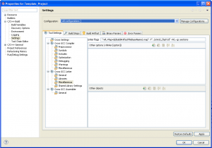
The -Wl flag tells GCC, "Pass this next little bit to the linker." The -Map=<path> argument tells the linker to generate a .map file. (I don't understand why this whole string needs to be in quotes, but it apparently does. I couldn't get it to work without quotes.) Your properties dialog should look like this:
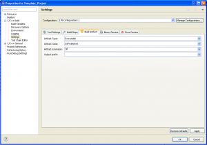
While we're here, let's make life a little easier on ourselves by adding an appropriate file extension to the linker output. Click on the Build Artifact tab. You should see that the Artifact Type is "Executable." In the Artifact extension textbox, give our linker output a .elf extension. Don't type the leading period before 'elf,' and be sure you select all configurations:
Click OK and build your project. When the build is finished, double-click the .map file (in Project Explorer, in the Debug folder, which holds all of the output from the build process when we build the Debug configuration of our project) to open it in the text editor. The first indication we have that something is wrong happens around line 24 of the .map output:
Memory Configuration

Name             Origin             Length             Attributes
*default*        0x00000000         0xffffffff
Clearly, the SMT32F0 doesn't have a single 4GB memory space. I am certainly no expert at reading .map files, but we can use some deductive logic to figure parts of it out. If we continue reading into the map file (my map file is here, if you want to take a peek), we start to see section names, such as .interp (line 68) and later, .init (line 138) and .text (line 150), along with the addresses at which those sections are loaded in the memory map. It looks like the linker put the .init section at 0x8000 in the memory map, and further sections went back-to-back from there. How or why the linker chose to start at 0x8000 is a mystery to me; if anyone can explain this, please put your thoughts in the comments. It appears that the linker first linked in functions from the built-in default libraries (libc.a, crti.o, crtbegin.o, crt0.o) and then our object files in the order in which they were passed on the command line. We can scroll through the .map file and find the address of every function in our object files.
When the Cortex-M0 exits reset, it fetches the top-of-stack address from memory location 0x00000000, and the reset vector from 0x00000004. When the boot mode configuration pins are configured to boot the microcontroller from FLASH ROM, the Flash memory address space at 0x08000000 is aliased to 0x00000000. (See section 2.5 of the reference manual.) Therefore, we need the linker to put the top-of-stack address at 0x08000000, then the reset vector, then the interrupt and exception vectors (section 11.1.3 of the reference manual), and then our code. The linker script is what tells the linker how to do all of this. I won't pretend to you that I can fully understand this file. I've read it, and studied it some, and there are some large questions still in my mind. But it's provided to us by the vendor (Atollic, in this case) and is known to work. We can tell the linker to use our script with the command line argument:
-T"..\stm32_flash.ld"
Add that to the linker arguments (Project properties, C/C++Build, Settings, Tool Settings tab, Cross GCC linker, Miscellaneous, Linker flags) and build your project again. Remember to add it to All Configurations. This time we get a warning from the linker that it couldn't find entry symbol Reset_Handler that's specified in the linker script, but the project did build. If we open our .map file, this time we see different results. For example, the memory configuration that the linker used now matches our physical part:
Memory Configuration

Name             Origin             Length             Attributes
FLASH            0x08000000         0x00010000         xr
RAM              0x20000000         0x00002000         xrw
MEMORY_B1        0x60000000         0x00000000         xr
*default*        0x00000000         0xffffffff
The .isr_vector section of the map is now placed at address 0x08000000, which is just where we want it. (It's 0x0 bytes long, though; we'll fix that shortly.) The .text section is 0x9e84 bytes long, which is about 40K of code. That's a lot of bloat for just blinking some LEDs; what we see here is that the entire peripheral library is included in the build even though we're not using most of the library functions. We'll fix that, too.
Let's first fix that problem with the Reset_Handler symbol. As it turns out, when we initially built our project, we didn't include some low-level startup code. This startup stuff can be found in the file startup_stm32f0xx.s, which is in \STM32F0\STM32F0xx_StdPeriph_Lib_V1.0.0\Libraries\CMSIS\Device\ST\STM32F0xx\Source\Templates\TrueSTUDIO. In our Project Explorer tree, create a new folder named "Startup." In the filesystem, copy the startup_stm32f0xx.s file into the project's startup folder. This file is an assembly code file. Double-click the file in Project Explorer to open it in the text editor. (Press F5 to refresh the Project Explorer view if necessary.) Even if you don't read assembly code, you can easily see that this file does define a symbol Reset_Handler.
Let's build our project again. Uh-oh. Nothing happened. If you right-click on startup_stm32f0xx.s, you'll see that the option "Build Selected File(s)" is greyed out. Eclipse doesn't know how to build a .s file. If you to to Project properties, C/C++ General, File Types, you'll see that our project is using workspace settings, and while there's a setting for .S files (with a capital letter S), there's no setting for .s (with a lowercase s) files. If you try to make an association for .s files, it won't work as expected. As it turns out, this has been a bug in Eclipse that has been known for a long time; there are apparently subtleties to getting this fixed that make a simple solution problematic. I was unable to find a solution within the GUI that would allow my .s file to assemble. The best solution, it seems, is to rename the file to have a .S (uppercase) extension. You can do this either in the filesystem or in the Project Explorer pane of Eclipse.
One last time, build your project. And... voilà! Our project has built without error.
We can see in the .map file that section .isr_vector is placed at memory location 0x08000000. This section, defined in startup_stm32f0xx.S, has the vector table for reset, interrupts, and system service calls. See Table 27 in section 11.1.3 of the Reference Manual for details.
We can take this a step further and look at a full disassembly of the project. I haven't found a linker command line argument to get it to output a full disassembly listing of the project (if anyone knows of one, please post in the comments), but we can use another tool in the toolchain to create a disassembly of our project. Open a command prompt and navigate so that the current working directory is the Debug folder of your project, and enter the command:
arm-none-eabi-objdump -D Template_Project.elf>Template_Project.lst
This command invoked objdump with the -D (disassemble all) argument to disassemble the file Template_Project, and uses the > operator to pipe the output to a file called Template_Project.lst. (Aren't you thankful that we decided to add the path to the ARM GCC binaries to the system path?) This command may take a while to complete, and the .lst file it generates is pretty huge. Nevertheless, it can be opened in the text editor. The first few lines are:
Disassembly of section .isr_vector:

08000000 <g_pfnVectors>:
 8000000:    20002000     ... <-- 0x20002000 is the top of the stack
 8000004:    08009a6d     ... <-- reset vector is 0x08009a6d
 8000008:    0800048d     ... <-- NMI vector
 800000c:    08000495     ... <-- HardFault vector
 etc.
Ignore the disassembly at these addresses; we want to interpret this data as vectors (addresses), not as machine code.
We can scroll through the .lst file and find the disassembly of address 0x08009a6d (the reset vector from the above disassembly):
08009a6c <Reset_Handler>:
 8009a6c:    480d          ldr    r0, [pc, #52]    ; (8009aa4 <LoopForever+0x2>)
 8009a6e:    4685          mov    sp, r0
 8009a70:    2100          movs    r1, #0
 8009a72:    e003          b.n    8009a7c <LoopCopyDataInit>
And in another part of the file:
0800048c <NMI_Handler>:
 800048c:    b580          push    {r7, lr}
 800048e:    af00          add    r7, sp, #0
 8000490:    46bd          mov    sp, r7
 8000492:    bd80          pop    {r7, pc}

08000494 <HardFault_Handler>:
 8000494:    b580          push    {r7, lr}
 8000496:    af00          add    r7, sp, #0
 8000498:    e7fe          b.n    8000498 <HardFault_Handler+0x4>
 800049a:    46c0          nop            ; (mov r8, r8)
Now, I can't account for the off-by-one difference in the addresses here (again, comments are appreciated), but I think that this should be sufficient to demonstrate that the linker did, in fact, do what we wanted it to do.
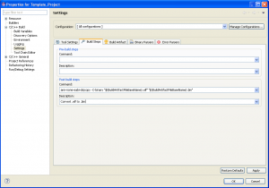
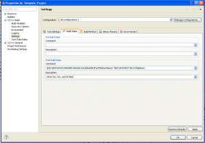
Let's solve that other problem we talked about. The compiled program weighs in at a little over 4MB. Now, to be fair, that's not 4MB of executable code. The output is in the .elf file format, which includes a bunch of other information, such as symbol information (which is how we were able to get symbols when we ran objdump on this file). We need to convert this to a .hex file to really get an idea of how much code we really have. (We'll also need a .hex file to upload the code to the dev board.) I poked around Eclipse quite a bit trying to add a new tool to my toolchain, but Eclipse would have none of it. Instead, we're going to have to run our .elf to .hex converter as a post-build step. In the project properties, go back to the C/C++ Build, Settings node of the tree. This time, click on the Build Steps tab, and add the following post-build step with a description "Convert .elf to .hex." Again, ensure "[All Configurations]" is your selected configuration. I forgot to do that in the screenshot below.
arm-none-eabi-objcopy -O binary "${BuildArtifactFileBaseName}.elf" "${BuildArtifactFileBaseName}.bin"
When we build again, we'll get a .bin file. And from that we can see that our compiled code is (roughly) 42K in size. As we mentioned, that's a bit bloaty for blinking some LEDs. What's happened here is that we've compiled all of the Standard Peripheral Library into our code. And even though we're not using the vast majority of those function calls, they're all in there in our finished product. There's no need to include code in our final output that will never be called. We can tell the linker to remove unused code (or, to be more precise, unused sections) by adding the linker flag --gc-sections (again, remember to add it to all configurations):
Now our .bin file is down to 10KB. That's better, but still... 10KB is an awful lot of code for a run-of-the-mill BlinkyLED program. Let's open that .map file and see what's going on. If you read through the file, you'll see that the linker excluded any object files that weren't needed from the final build. However, any object file that had even one needed function was included in its entirety into the linked program. This isn't what we want.
It turns out that the linker can only exclude "sections" from the final linked project. Either a section is included in its entirety, or it's excluded altogether. The linker isn't able to break a section up. When the compiler compiled each .c file, it created one .text section for the entire file. Therefore, we end up with a bunch of code in our final project that we don't need. The solution is to tell the compiler to create a separate section for each function. Let's add a -fdata-sections and a -ffunction-sections argument to the compiler to get this effect. As always, ensure you're performing this operation on all configurations:
Build one last time and in my case, my .bin file is 6K in size. It still seems a bit bulky for blinking a few LEDs, but a skim through the .map file confirms that the unneeded functions have indeed been stripped out of our final project:
Discarded input sections

 .text          0x00000000        0x0 c:/program files/gnu tools arm embedded/4.6 2012q2/bin/../lib/gcc/arm-none-eabi/4.6.2/armv6-m/crti.o
 .data          0x00000000        0x0 c:/program files/gnu tools arm embedded/4.6 2012q2/bin/../lib/gcc/arm-none-eabi/4.6.2/armv6-m/crti.o
 .bss           0x00000000        0x0 c:/program files/gnu tools arm embedded/4.6 2012q2/bin/../lib/gcc/arm-none-eabi/4.6.2/armv6-m/crti.o
 .data          0x00000000        0x4 c:/program files/gnu tools arm embedded/4.6 2012q2/bin/../lib/gcc/arm-none-eabi/4.6.2/armv6-m/crtbegin.o
 .text          0x00000000       0x6c c:/program files/gnu tools arm embedded/4.6 2012q2/bin/../lib/gcc/arm-none-eabi/4.6.2/../../../../arm-none-eabi/lib/armv6-m/crt0.o
 .data          0x00000000        0x0 c:/program files/gnu tools arm embedded/4.6 2012q2/bin/../lib/gcc/arm-none-eabi/4.6.2/../../../../arm-none-eabi/lib/armv6-m/crt0.o
 .bss           0x00000000        0x0 c:/program files/gnu tools arm embedded/4.6 2012q2/bin/../lib/gcc/arm-none-eabi/4.6.2/../../../../arm-none-eabi/lib/armv6-m/crt0.o
 .ARM.extab     0x00000000        0x0 c:/program files/gnu tools arm embedded/4.6 2012q2/bin/../lib/gcc/arm-none-eabi/4.6.2/../../../../arm-none-eabi/lib/armv6-m/crt0.o
 .ARM.exidx     0x00000000        0x8 c:/program files/gnu tools arm embedded/4.6 2012q2/bin/../lib/gcc/arm-none-eabi/4.6.2/../../../../arm-none-eabi/lib/armv6-m/crt0.o
 .text          0x00000000        0x0 ./src/main.o
 .data          0x00000000        0x0 ./src/main.o
 .bss           0x00000000        0x0 ./src/main.o
 .text._exit    0x00000000        0xc ./src/main.o
 .text          0x00000000        0x0 ./src/stm32f0xx_it.o
 .data          0x00000000        0x0 ./src/stm32f0xx_it.o
 .bss           0x00000000        0x0 ./src/stm32f0xx_it.o
Hey, we can see here that the _exit() function that we wrote is stripped out by the linker. Let's remove that from main.c now and rebuild.
You can see in the .map file that some of the functions in the peripheral library are rather bulky. We could rewrite our code to bypass the peripheral library and probably save quite a bit of code space, but that's outside the scope of this tutorial. This is as far as we're going to go in getting our project to build.
Step 6: Customize the Debug Build Configuration
Before proceeding, let's back up. Remember, we have two build configurations: Release and Debug. All of the changes we made to our environment so far were supposed to be made to all configurations. Let's build the Release version of the project to check that. In the Project menu, select Build Configurations -> Set Active -> Release. Then build. Any errors you encounter are likely due to a setting you made for the Debug build instead of All Configurations. After going through this exercise it should be straightforward for you to fix it. Flip back and forth between the two configurations and ensure that you can build both.
We want to make a few final changes. So far, our Debug and our Release build configurations are identical. (Actually, that's not strictly true; CDT has some built-in differences between the two, but work with me on this one for now.) That's really rather pointless. Let's change the Debug configuration so that, when we compile, there's a DEBUG symbol defined. That way, we can use the
[cc lang="c"]#ifdef DEBUG
#endif[/cc]
constructs in our code to conditionally compile code based on the build configuration. Add the symbol to the Debug configuration. Additionally, let's add the USE_FULL_ASSERT definition to add more error-checking to the Standard Peripheral Library when we test our Debug builds:
There we go... if you build this project, you build the demo program that comes preinstalled on the STM32F0DISCOVERY board.
Step 7: Install ST-LINK and Upload Code to the STM32F0DISCOVERY... and Debug Some More
The STM32F0DISCOVERY board has an onboard ST-LINK debugger. You can learn more about ST-LINK on ST's product page for the standalone version of the device. The documentation is somewhat open to interpretation, but it appears that ST-LINK can communicate with the target microcontroller via one of two interfaces: the SWIM interface, or the JTAG/SWD interface. The ST-LINK integrated into the STM32F0DISCOVERY board is connected to the STM32F0 via the SWD interface. (It would be interesting to determine if the JTAG interface is available from the integrated ST-LINK. It might be hard to test since some of the requisite signals from the embedded ST-LINK are not brought out to accessible points on the circuit board.) SWD claims to be a "2 wire" interface, but a common ground is of course necessary as well. In addition, access to the target system's VCC and RESET pins are also handy, but apparently not necessary, for SWD debugging. The SWD connector on the STM32F0DISCOVERY board can be used when using the STM32F0DISCOVERY board as a standalone ST-LINK programmer. The SWD connector is a 6-pin connector with VDD_TARGET, SWCLK, GND, SWDIO, NRST, and SWO pins.
Since the ST-LINK device and the STM32F0 target device are on the same physical circuit board, they already share a common ground and VCC. The other connections used in the Serial Wire Debug (SWD) connection are the SWCLK (PA14, pin 49), SWO (PB3, pin 55), NRST (pin 7) and SWDAT (PA13, pin 46). It appears that the STM32F0's PA9 and PA10 pins (the USART1 TX and RX ports) are wired between to the ST-LINK device as well, although to the best of my knowledge these pins are unused. (Perhaps a 'serial port debug' USB connection may be available through ST-LINK in the future?) The use of SWO/PB3 is 'reserved' according to the STM32F0DISCOVERY documentation and is governed by solder bridge 22. This bridge is connected on my board.
The ST-LINK debugger on the STM32F0DISCOVERY board is supported by a utility program that can be downloaded from ST's website. The ST-LINK Utility will allow us to upload our project to the dev board and run it, which is, after all, the ultimate point of this exercise. Go ahead and download the utility program. On ST's website, search for the ST-LINK product page. You'll find a page dedicated to the standalone version of the ST-LINK product. On the Design support tab of that page, download the "STM32 ST-LINK utility" in the Device Programmers section. Run the installer, which will add USB drivers for the ST-LINK. When you're done, launch the program.
From the File menu, select Open File. Browse to the Debug folder in your Template_Project folder, and double click on the Template_Project.bin file. You'll get a prompt to upload (or download, in the program's parlance) the file to the device. Click OK. Click 'Program' on the next dialog, and ST-LINK will upload the code and the STM32F0DISCOVERY board will run it!
At this point, I thought I was done.
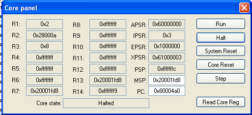
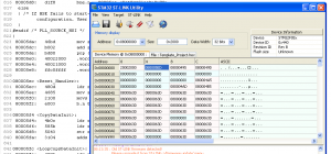
Unfortunately, if you use the ST-LINK utility to upload your code to your board, you'll find that it doesn't work. The LEDs don't blink. Nothing happens. As you might expect, this was frustrating for me when I was trying to get my build environment working. After sleeping on the problem overnight, I was able to make some progress. The ST-LINK utility has only the most rudimentary debugging facilities. I was able to see that the processor was apparently stuck in an endless loop at address 0x080004a0. I found this by going to Target-> MCU Core and clicking on the System Reset button to run the code, then when nothing happened, I clicked the Halt button. The Program Counter (PC) register was at 0x080004a0, and clicking the Step button didn't advance the PC.
To debug this, I opened a command prompt and navigated to the Debug build output of my Eclipse project and ran the command:
arm-none-eabi-objdump -S template_project.elf>template_project.lst
to get a disassembly of the compiled project and found that the address at which the processor was spinning is the HardFault_Handler routine in stm32f0xx_it.c, which indeed is written as an infinite loop. Finding out how I got here was a bit more challenging. I started by changing my post-build step to produce not only the .bin file, but also a .hex file and a .lst file. Since Eclipse seems to only allow a single post-build step (again, if anyone knows differently, please comment on the post), I wrote a batch file to do the work:
[cc]set BasePath=%2
REM replace forward slashes with backslashes
set BasePath=%BasePath:/=\%
REM remove quotes
set BasePath=%BasePath:"=%
REM append configuration directory
set BasePath=%BasePath%\%3
set BuildArtifactPathAndBaseName=%BasePath%\%1
arm-none-eabi-objcopy -O binary %BuildArtifactPathAndBaseName%.elf %BuildArtifactPathAndBaseName%.bin
arm-none-eabi-objcopy -S -O ihex %BuildArtifactPathAndBaseName%.elf %BuildArtifactPathAndBaseName%.hex
arm-none-eabi-objdump -S %BuildArtifactPathAndBaseName%.elf>%BuildArtifactPathAndBaseName%.lst[/cc]
I put the batch file in my project folder, in a new folder called "PostBuild," and changed the post-build step in Eclipse to:
Now, whenever I build my project, I automatically get a .bin file, a .hex file, and a .lst file. Very useful.
Edit 9/17/2012: Adding the command "arm-none-eabi-size %BuildArtifactPathAndBaseName%.elf" to the end of the file will get you output that shows the size of your compiled project, if you'd like to add this as well.
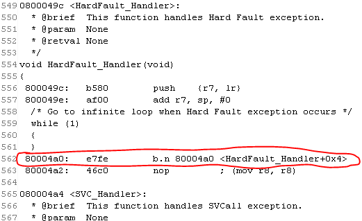
Now let's figure out how we got into the hard fault handler. I rebuilt my project to ensure that my .bin and .lst files match up (make sure you set your active build configuration to Debug first!), then used ST-LINK to upload my code to the STM32F0DISCOVERY board. In the Target-> MCU Core menu dialog, I reset the processor and clicked Halt. I verified that clicking the 'Step' button did not advance the program counter (PC register). I then used the .lst file to verify that I'm in the hard fault handler's infinite loop:
The circled instruction in the .lst file is the infinite loop.
Unfortunately, there's no way to set a breakpoint with ST-LINK. Once the processor is halted, registers and memory can be read (but apparently not written to) but that's about it. I can, for instance, see that the reset vector in the chip's flash memory (address 0x08000004, which currently holds value 0x080005ED) does indeed match the Reset_Handler in the .lst file (at memory location 0x080005EC):
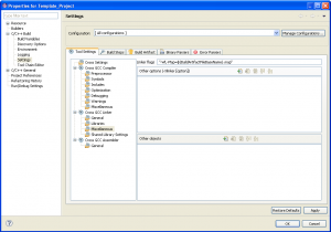
After a very frustrating weekend of troubleshooting, I was able to solve this with some additional debugging tools (I'll save that for a later post) and a thread I started on ST's community website. It turns out that the Hard Fault was caused by an attempt to switch the CPU to ARM mode, instead of Thumb mode. The Cortex-M0 doesn't support the ARM instruction set. The solution is to add two linker flags:
-mthumb -mcpu=cortex-m0
Be sure to do this for all configurations:
Build your project. Upload to the STM32F0DISCOVERY board with the ST-LINK Utility. Reset the processor. Behold the blinkylights.
And yes, do the Happy Dance.
Next: Creating a Template for Future Projects
I think that's enough for this post. In my next entry, we'll do some housekeeping on this project to turn it into a true template that can be copied for later projects. We'll then use that template to create a custom BlinkyLED program that we can use to validate our build environment. We'll integrate a debugger into the Eclipse environment for source-level debugging, and after that, the world (or at least the STM32F0) is our oyster.








Great Post! I particularly like how you used the basic debugger in the ST Link Utility. Keep up the good work!
You are my new best friend! I googled “STM32F0DISCOVERY” and got this post. I think a free toolchain for the STM32Discovery board that “just works” is a huge step forward for adoption. Thank you for your great post.
Thanks so much for this great tutorial! I’ve been struggling with other partial tutorials online but this one (walking through the various errors) was by far the most helpful and now I feel like I understand what is going on a lot more.
Two little notes:
– Near the end you say to add “-mthumb -mcpu=cortex-mo” to the linker flags, though in the image you have correctly entered “-mthumb -mcpu=cortex-m0” (it needs to be 0, o doesn’t fix the problem – as I discovered 😉
– I had a couple additional errors in my main.c file. After you had reached the point where the program was successfully compiling I still had two errors that read, “Symbol ‘TimingDelay’ could not be resolved” and the declaration of static __IO uint32_t TimingDelay; was flagged with a syntax error. It took a bit of troubleshooting, but (because I had followed through the errors and solutions for other problems you described) I was able to solve the problem. I needed to replace “__IO” with just “volatile” or (my preferred solution) I added #include “core_cm0.h” to the beginning of main.c. After that everything was fine. Any idea why I encountered that problem?
Thanks again for the great walkthough!
Graeme, thanks for the comment! I just fixed the typo you pointed out in the linker flags. Thank you for pointing that out to me.
I don’t know why your code couldn’t find TimingDelay when you built your project. I didn’t have that problem. You’ll have to look at the errors that the build process gives you and determine in which file the error is occurring, and go from there. I’m afraid that I’m not a very good C programmer nor am I an expert in the Eclipse/GCC toolchain… I just happened to have more determination than sense when I set out to figure this stuff out. I’m sure that you’ll find the problem that’s causing your build errors with a little more investigation.
Hi Matthew,
Thanks for putting up this post. I am yet to go through the page completely. With regards to the FW version mentioned, the code is now V-1.0.1 released on 20-April-2012 as mentioned in the source code of the ST Std Peripheral library.
In stm32f0xx.h
00144 #define __STM32F0XX_STDPERIPH_VERSION_MAIN (0x01) /*!< [31:24] main version */
00145 #define __STM32F0XX_STDPERIPH_VERSION_SUB1 (0x00) /*!< [23:16] sub1 version */
00146 #define __STM32F0XX_STDPERIPH_VERSION_SUB2 (0x01) /*!< [15:8] sub2 version */
00147 #define __STM32F0XX_STDPERIPH_VERSION_RC (0x00) /*!< [7:0] release candidate */
The top folder name is what they got wrong this time i.e. STM32F0xx_StdPeriph_Lib_V1.0.0 instead of STM32F0xx_StdPeriph_Lib_V1.0.1.
Thanks again for doing this.
Hi Matthew
First of all please let me say a big thank you for the tutorial/walk through.
Your approach of illustrating the problems & solutions so fully really gave me a good understanding of how things work.
Unfortunately, I’m stuck at the very last part!
I have almost exactly the problem you describe above where the processor is stuck in the hardfault handler loop.
In my case, strangely, the address was 0x08000158.
I’ve cheked that the ‘-mthumb -mcpu=cortex-m0’ switches are set. It’s slightly different for my setup since I’m using Eclipse Juno that has explicit check boxes for these switches.
The only other thing of note is that I’m using the gnu arm plugin : org.eclipse.cdt.cross.arm.gnu_0.5.4.201202210114.
I’ve checked that it can run thumb and it does.
What’s suspicious is that my HardFault_Handler is at address 0x08000158 rather than at address 0x080005EC.
I hope you can give me some guidance with this problem.
Many thanks in advance.
Gerry Murray
Glasgow
Scotland
Hi again Matthew
One thing I would be very grateful of is a zip file with the lst, elf, map and hex files from your successfully built template project.
Doing a diff between your files and mine might give me a clue as to what’s going wrong with my process.
Having an image of all the files on a successful build might help others going through the same process too.
Many thanks again for a great tutorial.
Gerry Murray
Success at last!
Hi Matthew.
I resolved my problems. It was down to a couple of things:
1. There were a couple of gnu arm commands that I’d inserted without quotes in the command line.
I had :
C:\Program Files (x86)\GNU Tools ARM Embedded\4.6 2012q4\bin\arm-none-eabi-gcc
instead of :
“C:\Program Files (x86)\GNU Tools ARM Embedded\4.6 2012q4\bin\arm-none-eabi-gcc”
2. I had the reference to my linker script in double quotes.
All it really needed in the end was to RRTFM : RE-read the f****n manual. 🙂
Thanks again.
Gerry Murray
Gerry, I’m glad to hear you’re up and running! I apologize for not replying sooner; my attentions have been on spendign Thanksgiving with the family and building a workshop. (Look for that in upcoming blog posts.)
Hi Matthew
Happy Thanksgiving! We ‘Jocks’ don’t celebrate that so I always forget.
Cheers
Gerry Murray
Glasgow
Scotland
Same problem as Graeme:
>> uint32_t and TimingDelay error messages.
Both went away when I restarted Eclipse.
Mathew, Love the blog. Please keep it up.
Same problem as Graeme:
>> uint32_t, uint8_t, and TimingDelay error messages.
After some googlebinging on the error message, I did a [ProjectName]>Index>Rebuild and all problems went away.
I have a blinky LED now. 🙂
Mathew, Love the blog. Please keep it up.
Dear matthew,
The tutorial is great. I got my blinky leds demo error and warninglessly build:
Build complete for project Template_Project
Only when I program my stm32f0c6 discovery I run into some problems. The stlink programs the flash of the mcu fine, it even verifies it. Except I can’t run the blinking led program, nor are either of the two leds lit up. Now, when I look to the Mcu core overview panel. It says that the core state is Lockup. I have no idea how the fix this. Or where to look in fixing this. Any idea’s?
He mathew,
I fixed the problem myself. It had something to do with my assembler. It missed some flags in assembling the startup file. Also, i had the wrong startup file, therefor it would not build the way it should have.
Thanks again
~bart
Hello,
Thanks a lot for your great work..! 🙂
to set multiple post-build steps in Eclipse, you just have to separate them with a semi-colon.
I just tried this one successfully on my Juno Eclipse :
arm-none-eabi-objcopy -O binary “${BuildArtifactFileBaseName}.elf” “${BuildArtifactFileBaseName}.bin”; arm-none-eabi-objcopy -S -O ihex “${BuildArtifactFileBaseName}.elf” “${BuildArtifactFileBaseName}.hex”; arm-none-eabi-objdump -S “${BuildArtifactFileBaseName}.elf” > “${BuildArtifactFileBaseName}.lst”; arm-none-eabi-size “${BuildArtifactFileBaseName}.elf”
Thanks again..
Fred
Matthew,
Kudos to you for putting this together and maintaining it so well. Based on the information, I was able to get my toolchain up and running with the STM32F3Discovery demo. It would have taken me much longer to get where I am without your fine work.
Thanks!
— Paul S
A small side note: For Windows users trying to chain together multiple post-build steps, substitute “&” for “:” in Fred’s comment above.
Hello,
I’m working on Windows too.. just tried to install on another computer and copy my postbuild chain from here and it didn’t worked. had to correct the ” character that is not the standard one on this webpage to make it work…
Cheers. Excellent way of writing up a tut! The clock tool part was a great insight, helped me even for my Keil dev setup.
Best wishes
hello,
first of all i want to thank you for this tutorial, it is realy helpfull.i am new to arm programming and i try to set my tools . I have followed your instructions but i have a problem when it comes to gcc flags. i have a stm32f4 board and when it cames to pass the flags in the textbox (in my case -mthumb -mcpu=cortex-m4 -mfloat-abi=hard -mfpu=fpv4-sp-d16 ) i get some errors:
gcc: error: unrecognized command line option ‘-mfpu=fpv4-sp-d16’
gcc: error: unrecognized command line option ‘-mfloat-abi=hard’
gcc: error: unrecognized command line option ‘-mthumb’
i dont know what the problem is , because those instructions are given with the readme.txt file and also worked for your board
if you know what the problem is, i would be very happy if you reply.
thank you again
Dimitris,
You fail to specify which textbox you entered those flags into. Start troubleshooting by getting the full command that Eclipse launched from the console window. Find out what executable was called, and go through all the arguments that Eclipse passed to the program.
Great tutorial! Thanks so much! Managed to get it working in Eclipse Kepler.
I found a GNU ARM Eclipse plugin over at http://sourceforge.net/projects/gnuarmeclipse/. (The Eclipse update site is http://gnuarmeclipse.sourceforge.net/updates).
It’s pretty useful. It’s a toolchain basically, and it adds in GUI settings for a lot of the options that are done with commands here. For example, setting the arm family to m0 and instruction set to mthumb is an option in the settings, so it applies to the compiler and linker, and the error due to mthumb not being set in step 7 doesn’t happen. It also has some more options for setting up projects for different arm processors (STM included of course).
The setup is slightly different, but nothing a bit of poking around won’t solve.
Also just want to point out, the latest version of the Standard Peripheral Library (v1.3.1) no longer has the STM32F0_DISCOVERY folder, but I just copied it across from the STM32F0-Discovery_FW_V1.0.0 and everything worked fine.
One thing I found out the hard way, the .bin file generated by the release configuration doesn’t work (my program counter is stuck at 0x80001fe). However, I have the file generated by the debug configuration is working, so I’m not too fussed.
Has anyone got their release config producing a bin file that gets the lights flashing please? My settings of the two configurations seem the same to me.
Thanks again for this great tutorial. Just thought I’d share back what I’ve learnt. If anyone is stuck getting the GNU ARM plugin/Kepler to work feel free to drop me a mail at johnlewis0945 [at]gmail[dot]com and I’ll see if I can help.
dear Matthew,
I followed his guidance.
The single difference is that the eclipse and the cross-compiler are more current.
I managed to remove all compilation errors, but…
Something unexpected happened at the end.
The following error occurred:
problems tab
============
Description: make: *** [TEMPLATE] Error 1
Resource: TEMPLATE
Type: C/C++ Problem
console tab
===========
12:49:41 **** Build of configuration Debug for project TEMPLATE ****
“L:\\GnuWin32\\bin\\make.exe” all
‘Building target: TEMPLATE’
‘Invoking: Cross GCC Linker’
arm-none-eabi-gcc -o “TEMPLATE” ./src/main.o ./src/stm32f4xx_hal_msp.o ./src/stm32f4xx_it.o ./src/system_stm32f4xx.o ./HAL_driver/src/stm32f4xx_hal.o ./HAL_driver/src/stm32f4xx_hal_adc.o ./HAL_driver/src/stm32f4xx_hal_adc_ex.o ./HAL_driver/src/stm32f4xx_hal_can.o ./HAL_driver/src/stm32f4xx_hal_cortex.o ./HAL_driver/src/stm32f4xx_hal_crc.o ./HAL_driver/src/stm32f4xx_hal_cryp.o ./HAL_driver/src/stm32f4xx_hal_cryp_ex.o ./HAL_driver/src/stm32f4xx_hal_dac.o ./HAL_driver/src/stm32f4xx_hal_dac_ex.o ./HAL_driver/src/stm32f4xx_hal_dcmi.o ./HAL_driver/src/stm32f4xx_hal_dma.o ./HAL_driver/src/stm32f4xx_hal_dma2d.o ./HAL_driver/src/stm32f4xx_hal_dma_ex.o ./HAL_driver/src/stm32f4xx_hal_eth.o ./HAL_driver/src/stm32f4xx_hal_flash.o ./HAL_driver/src/stm32f4xx_hal_flash_ex.o ./HAL_driver/src/stm32f4xx_hal_flash_ramfunc.o ./HAL_driver/src/stm32f4xx_hal_gpio.o ./HAL_driver/src/stm32f4xx_hal_hash.o ./HAL_driver/src/stm32f4xx_hal_hash_ex.o ./HAL_driver/src/stm32f4xx_hal_hcd.o ./HAL_driver/src/stm32f4xx_hal_i2c.o ./HAL_driver/src/stm32f4xx_hal_i2c_ex.o ./HAL_driver/src/stm32f4xx_hal_i2s.o ./HAL_driver/src/stm32f4xx_hal_i2s_ex.o ./HAL_driver/src/stm32f4xx_hal_irda.o ./HAL_driver/src/stm32f4xx_hal_iwdg.o ./HAL_driver/src/stm32f4xx_hal_ltdc.o ./HAL_driver/src/stm32f4xx_hal_nand.o ./HAL_driver/src/stm32f4xx_hal_nor.o ./HAL_driver/src/stm32f4xx_hal_pccard.o ./HAL_driver/src/stm32f4xx_hal_pcd.o ./HAL_driver/src/stm32f4xx_hal_pcd_ex.o ./HAL_driver/src/stm32f4xx_hal_pwr.o ./HAL_driver/src/stm32f4xx_hal_pwr_ex.o ./HAL_driver/src/stm32f4xx_hal_rcc.o ./HAL_driver/src/stm32f4xx_hal_rcc_ex.o ./HAL_driver/src/stm32f4xx_hal_rng.o ./HAL_driver/src/stm32f4xx_hal_rtc.o ./HAL_driver/src/stm32f4xx_hal_rtc_ex.o ./HAL_driver/src/stm32f4xx_hal_sai.o ./HAL_driver/src/stm32f4xx_hal_sd.o ./HAL_driver/src/stm32f4xx_hal_sdram.o ./HAL_driver/src/stm32f4xx_hal_smartcard.o ./HAL_driver/src/stm32f4xx_hal_spi.o ./HAL_driver/src/stm32f4xx_hal_sram.o ./HAL_driver/src/stm32f4xx_hal_tim.o ./HAL_driver/src/stm32f4xx_hal_tim_ex.o ./HAL_driver/src/stm32f4xx_hal_uart.o ./HAL_driver/src/stm32f4xx_hal_usart.o ./HAL_driver/src/stm32f4xx_hal_wwdg.o ./HAL_driver/src/stm32f4xx_ll_fmc.o ./HAL_driver/src/stm32f4xx_ll_fsmc.o ./HAL_driver/src/stm32f4xx_ll_sdmmc.o ./HAL_driver/src/stm32f4xx_ll_usb.o
l:/gnu tools arm embedded/4.8 2014q2/bin/../lib/gcc/arm-none-eabi/4.8.4/../../../../arm-none-eabi/lib\libc.a(lib_a-exit.o): In function `exit’:
exit.c:(.text.exit+0x2c): undefined reference to `_exit’
collect2.exe: error: ld returned 1 exit status
make: *** [TEMPLATE] Error 1
12:49:49 Build Finished (took 7s.580ms)
Could you help-me with this?
dear Matthew,
Sorry me, forgot to mention that I’m using STM32F429I-DISCO board.
Hello,
I just find your Website.
I am looking for a solution to uncompiler a sound data file extension .snd off a telemetry box system only in german or english
This material is stopped build by german company and obviously nos more langage.
Do you have an idee to help me to try change after uncompiled the file to change vocable sound in French.
the ARM is a 35F100 type
There is a com port on the box to load main prg and the language file
Many thanks in advance for reply
Have a nice Day
Daniel
Use an & to separate multiple post build cmds, then you won’t have to use a batch file !
I spent about 5 days seriously tinkering with Eclipse, attempting to compile/make/link an arbitrary sample file from the mbed sample directory – such as ‘FileTest’ for LPC1768. I’m a newbie at Eclipse. I kept encountering wave after wave of issues like ‘file or directory not found’, ‘localfilesystem not found’, ‘undefined reference to exit_’ etc etc. I was reading up on so much information from the internet to try gather information to sort out all of these things. But it became apparent that it’s virtually impossible to figure out how to get things to properly compiled and linked without the help of people like Matthew here. I only ‘just’ came across this particular thread and saw Matthew’s phenomenal effort in teaching everybody here what to do, what issues to expect, and how to overcome them – in a very complete way. Other information from the internet address certain issues, but hardly anybody gave a decent answer about how to properly deal with ‘undefined reference to _exit’ etc etc. A genuine thanks to you Matthew. You are a true teacher.
Well done! I’m an experienced engineer who’s been using these tools for a long time, and I’ve never come across such a thorough, yet simple, explanation of what everything does and how to use it. This is a marvelous example of how to set up a build environment without the aid of a pre-packaged IDE from a commercial vendor. This is an outstanding contribution to the arm development community.
Hi,
After I did build, even though there were no errors, I could not find the executable file in the Debug or Release folder. Can someone help me how to solve this?
Is it possible to exclude newlib from build?
Matthew, I should have thanked you in my previous post for what is one of the best and most thorough tutorials on setting up an ARM toolchain.
Thank you sir. Really nice information. I was looking for it from last few days. This will help me to built my project. Thank a lot.
https://www.olimex.com/Products/ARM/_resources/ARM-Cross-Development-with-Eclipse-version-3.pdf
This very old article goes into great detail about everything surrounding this project, but of course if way out of date. Still an excellent read. The whole second half is about programming the ARM chip, likewise going into great detail.
Damn! Found in 2022 what I was looking for! Very comprehensive article! Reading every error’s solution was so interesting, the solution explanation is amazing.
I didn’t understood why this is obsolete? Yes, there new versions of software, HW, etc. Even tedious Eclipse(Eclipse and toolchain setup), but workflow didn’t change when using GCC.