In late 2012, I wrote a five-part series of tutorials on getting started with the ARM GCC Compiler on Windows for the STM32F0Discovery board. You can review part one, part two, part three, part four, and part five.
Today I want to do the same thing but show you how to get up and running with the STM32F4DISCOVERY board. The STM32F4 parts are more capable than the STM32F0 parts. In particular, the STM32F4 series has a Cortex-M4 processor with hardware floating point unit, is faster, and has more memory than the F0 parts. The chip on the STM32F4DISCOVERY kit has 1MB FLASH and 192K of RAM. These are very generous amounts of memory for a microcontroller!
Here's the ST feature list for the STM32F4DISCOVERY board:
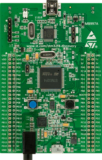
Key Features
- STM32F407VGT6 microcontroller featuring 32-bit ARM Cortex-M4F core, 1 MB Flash, 192 KB RAM in an LQFP100 package
- On-board ST-LINK/V2 with selection mode switch to use the kit as a standalone ST-LINK/V2 (with SWD connector for programming and debugging)
- Board power supply: through USB bus or from an external 5 V supply voltage
- External application power supply: 3 V and 5 V
- LIS302DL or LIS3DSH ST MEMS 3-axis accelerometer
- MP45DT02, ST MEMS audio sensor, omni-directional digital microphone
- CS43L22, audio DAC with integrated class D speaker driver
- Eight LEDs:
- LD1 (red/green) for USB communication
- LD2 (red) for 3.3 V power on
- Four user LEDs, LD3 (orange), LD4 (green), LD5 (red) and LD6 (blue)
- 2 USB OTG LEDs LD7 (green) VBus and LD8 (red) over-current
- Two push buttons (user and reset)
- USB OTG FS with micro-AB connector
- Extension header for all LQFP100 I/Os for quick connection to prototyping board and easy probig
Here's a consolidated list of steps to get up and running. Please see my earlier tutorial series for a full explanation of each step and what it does.
- Install ARM GCC from this website. Be sure to check "Add path to environment variable" on the last page of the wizard. (Reference)
- Install the GCC MAKE utilty from this link. Download the "Complete package, except sources" file. Accept defaults in the setup wizard. (Reference)
- Download and install the GNU utilities package for Windows. When finished, add the path to the folder containing the binaries to your system path. This installs the "rm" command so that the "Clean Project" option will work.
- Create a Development folder and a Workspace folder. Choose paths with no spaces in them. (Reference)
- Install Eclipse on your machine (Reference)
- Install CDT, Cross-Compiler support, and GCC Hardware Debugging support within Eclipse. Install the ST-LINK utility. (Reference, Reference)
- Within your workspace folder, create two subfolders named 'Libraries' and 'Projects.' (This is a different folder structure than I used in the STM32F0 tutorial series.)
- Download the STM32F4 DSP and standard peripherals library from ST's website. Extract the files into the Libraries folder.
- Launch Eclipse and open your workspace folder when prompted to open a workspace.
- Create a new project. (File... New... Project)
- Select the C Project wizard in the C/C++ node of the treeview control
- Name the new project "STM32F4_TemplateProject" and override the default path to put the new project inside the Projects folder. Ensure the Cross GCC toolchain is selected.
- Enter the cross compiler prefix "arm-none-eabi" and the path
- Within the IDE, create a src and an inc folder. Inside the src folder, create a Startup folder. (Again, this is a different file structure than I used in my STM32F0 tutorial. Do what works for you.)
- The sample program that ships with the STM32F4DISCOVERY kit uses the USB port to emulate a mouse. That's a bit ambitious for our first 'hello, world' program. Instead of building the demo program from ST, we're going to build a program that turns on the green LED when it runs, and turns on the blue LED whenever the USER button is pressed. To do this, we're going to have to copy some of the sample files into our project directory and then edit them. The files we need are in the STM32F4xx_StdPeriph_Lib_V1.3.0\Project\STM32F4xx_StdPeriph_Templates folder. Copy main.c, stm32f4xx_it.c, and system_stm32f4xx.c to our project's src folder. Copy main.h, stm32f4xx_it.h, and sym32f4xx_conf.h to the inc folder. From the STM32F4xx_DSP_StdPeriph_Lib_V1.3.0\Project\STM32F4xx_StdPeriph_Templates\TrueSTUDIO\STM32F40_41xxx folder, copy STM32F407IG_FLASH.ld to the root of the Project folder. From the STM32F4xx_DSP_StdPeriph_Lib_V1.3.0\Libraries\CMSIS\Device\ST\STM32F4xx\Source\Templates\TrueSTUDIO folder, copy startup_stm32f401xx.s to the src/startup folder in your project. Rename the file from having a .s (lowercase) extension to a .S (uppercase) extension.
- In the Eclipse IDE, select the root of the project tree and refresh so that the IDE sees all of the changes we made to the filesystem.
- Right-click the src folder and select New Folder. Click the advanced button and select linked folder. Name the folder StdPeriph and use the location WORKSPACE_LOC\Libraries\STM32F4xx_DSP_StdPeriph_Lib_V1.3.0\Libraries\STM32F4xx_StdPeriph_Driver\src. (Reference)
- In the project properties, C/C++ General, Paths and Symbols node, click on the Includes tab, click GNU C and ensure All Configurations is selected. Add the following include paths:
- ${ProjDirPath}/inc
- ${WorkspaceDirPath}/Libraries/STM32F4xx_DSP_StdPeriph_Lib_V1.3.0/Libraries/CMSIS/Device/ST/STM32F4xx/Include
- ${WorkspaceDirPath}/Libraries/STM32F4xx_DSP_StdPeriph_Lib_V1.3.0/Libraries/CMSIS/Include
- ${WorkspaceDirPath}/Libraries/STM32F4xx_DSP_StdPeriph_Lib_V1.3.0/Libraries/STM32F4xx_StdPeriph_Driver/inc
- In the project properites, C/C++ Build, Settings node, click on Cross GCC Compiler, Symbols. Ensure All Configurations is selected. Add the following two symbols:
- STM32F40_41xxx
- USE_STDPERIPH_DRIVER
- Add the following build flags under project properties, C/C++ Build, Settings, Cross GCC Compiler, Miscellaneous. Ensure All Configurations is selected.
- -c -fmessage-length=0 (should already be there)
- -mthumb
- -mcpu=cortex-m4
- -mfloat-abi=hard
- -mfpu=fpv4-sp-d16
- -fdata-sections
- -ffunction-sections
- Add the following linker flags under project properties, C/C++ Build, Settings, Crogg GCC Linker, Misellaneous. Ensure All Configurations is selected.
- -Wl,--gc-sections
- -T"..\STM32F407IG_FLASH.ld"
- "Wl,-Map=${BuildArtifactFileBaseName}.map"
- -mthumb
- -mcpu=cortex-m4
- -mfloat-abi=hard
- -mfpu=fpv4-sp-d16
- In project settings, C/C++ Build, Settings node, Build Artifact tab, set the Artifact extension to "elf"
- In project settings, C/C++ Build node, Builder Settings tab, uncheck "Use default build command" and enter the command "C:\Progra~1\GnuWin32\bin\make.exe"
- In the project explorer window, expand the src folder, then the StdPeriph folder. Right-click on the stm32f4xx_fmc.c file and select "Resource Configurations... exclude from build." Click Select All and click OK.
- Add the following #defines to your main.h file:
[cc lang="c"]#define GREEN_LED_PORT GPIOD
#define GREEN_LED_PIN GPIO_Pin_12
#define BLUE_LED_PORT GPIOD
#define BLUE_LED_PIN GPIO_Pin_15
#define USER_BUTTON_PORT GPIOA
#define USER_BUTTON_PIN GPIO_Pin_0
#define BLUE_LED_PERIPH_CLOCK RCC_AHB1Periph_GPIOD
#define GREEN_LED_PERIPH_CLOCK RCC_AHB1Periph_GPIOD
#define USER_BUTTON_PERIPH_CLOCK RCC_AHB1Periph_GPIOA
#define USER_BUTTON_IS_PRESSED (USER_BUTTON_PORT->IDR & USER_BUTTON_PIN)[/cc]
- Add the following code to main():
[cc lang="c"]//enable clocking to the GPIO ports
RCC_AHB1PeriphClockCmd(GREEN_LED_PERIPH_CLOCK, ENABLE);
RCC_AHB1PeriphClockCmd(BLUE_LED_PERIPH_CLOCK, ENABLE);
RCC_AHB1PeriphClockCmd(USER_BUTTON_PERIPH_CLOCK, ENABLE);
//Set up the pins for the LEDs and User Button
GPIO_InitTypeDef gpioInit;
gpioInit.GPIO_Mode = GPIO_Mode_OUT;
gpioInit.GPIO_OType = GPIO_OType_PP;
gpioInit.GPIO_Pin = GREEN_LED_PIN;
gpioInit.GPIO_PuPd = GPIO_PuPd_NOPULL;
gpioInit.GPIO_Speed = GPIO_Speed_50MHz;
GPIO_Init(GREEN_LED_PORT, &gpioInit);
gpioInit.GPIO_Pin = BLUE_LED_PIN;
GPIO_Init(BLUE_LED_PORT, &gpioInit);
gpioInit.GPIO_Mode = GPIO_Mode_IN;
gpioInit.GPIO_Pin = USER_BUTTON_PIN;
GPIO_Init(USER_BUTTON_PORT, &gpioInit);
//Turn on the green LED
GREEN_LED_PORT->BSRRL |= GREEN_LED_PIN;
//Turn off the blue LED
BLUE_LED_PORT->BSRRL |= BLUE_LED_PIN;
/* Infinite loop */
while (1)
{
╥╥╥if (USER_BUTTON_IS_PRESSED)
╥╥╥{
╥╥╥╥BLUE_LED_PORT->BSRRH |= BLUE_LED_PIN;
╥╥╥}
╥╥╥else
╥╥╥{
╥╥╥╥BLUE_LED_PORT->BSRRL |= BLUE_LED_PIN;
╥╥╥}
}[/cc]
Build your project and debug it using the steps in the previous tutorial.
Let me know how things work for you!
The Standard Peripheral Library is configured for a demo board with a 25MHz crystal. The STM32F4DISCOVERY has an 8MHz crystal onboard. As a result, computations regarding clock frequency may not be accurate if you build with this file. To fix this, change the value of HSE_VALUE in stm32f4xx_conf.h from its current value of 25,000,000 to a value of 8,000,000. You may also wish to download ST's Clock Configuration tool (which is actually an Excel spreadsheet) and build a new system_stm32f4xx.c file with a set of known-good clock values.
I got the compile to work but it complains about “USER_BUTTON_IS_PRESSED” is not found. Don’t see a definition for that.
Also eclipse complains about unit32_t as not being defined, but doesn’t effect the compile.
You also don’t explain how to get the code onto the board.
I have both the STM32F401C-DISCO and STM32F429I-DISCO.
I have been using the Parallax Propeller Activity Board which compared to these units is childs play to program.
3DRobotics is using this chip in there PIXHAWKS units for flight navigation. Was looking to see how it works.
Mike
Mid life retiree with idle hands
Michael, I don’t know how I missed that macro. Add a line to your project:
#define USER_BUTTON_IS_PRESSED (USER_BUTTON_PORT->IDR & USER_BUTTON_PIN)
The uint32_t type is declared in stdint.h, which is included in stm32f4xx.h, which is included in main.h in my project. Whether I added that without realizing that as I wrote this tutorial, or it came from the main.h that I copied from another project, I do not know.
I encourage you to read my series of posts on setting up a build environment for the STM32F0DISCOVERY. This post is a summary of information that is explained in great detail in those older posts.
Yes, setting up a build environment for these chips is significantly more involved than some other chips. The hardware vendors for ARM chips tend to rely on independent software vendors to support the build environment. If you’re willing to pay for this software I imagine it’s a lot easier to get up and running. For us hobbyists trying to do things for cheap/free, we have to jump through a few more hoops.
Ok, I found the section on ST-LINK and got that utility.
My biggest fear is that I will lost the program that works on the board and will have nothing but a bad board. Well I was able to load the board and then load back the original demo code.
Your code however just causes a hard fault. Don’t know what the final code should look like. The addresses seem correct but no joy on the code.
Having some issues with eclipse going sideways and losing or corrupting the configuration.
Just to blink some LED’s there is a lot of code. The Propeller chip on the other hand only needs a couple of lines. Set Pin direction to output and set pin to high.
Mike
Hello,
your blog has been very useful in helping me setup my computer to work with the STM32f429IDISCOVERY board.
I am able to build my code now, and to upload binaries on the board (I am pretty much a beginner with regards to embedded, so this kinda is something for me).
I have been trying to build a program to cause the green LD3 to blink, using the STM32CubeMX utility to set things up. It automatically copies all drivers and things, saving me some time in looking for them in the st firmware folders. I edited the setting for the GPIO to try and configure the PG13 that is connected to the green LED (the tutorial I am using is found in the utility’s manual, but it is written for a previous board, so the GPIO connected to the LED were different). Everything builds ok, but nothing blinks on the board after I download my software.
I was wondering if you had any experience with this tool, and/or if you could give me some pointers. My googling bore no fruit.
Keep up the nice blog.
Matteo
Matteo,
Thanks for your kind feedback. Before you try to get your custom code to work, are you able to get my demo code (or anyone’s demo code) to work on the board? Let’s start there. If that doesn’t work, send me your source code in an email and I’ll see if I can find anything. Remember, though, that I’m not an expert at this; I’m just an idiot with a blog. Working with the STM32 parts can have a steep learning curve. If we can’t figure it out together, I’d suggest you try ST’s forums.
Hello,
Thanks for replying.
The demo code I donwloaded from st works. I figure i have a problem wih setting something up and I should dig deeper in the manuals to understand what. So far my attempts to hack the headers and c files automatically set up with stmcube gave no result, so I will just start from scratch, set things up differently in stmcube and then hunt for code differences if that works.
so far the forums and google have not given me much info on that tool.
best,
Matteo
Hello,
I have an update on my issues.
I had not correctly set up the linker flags for my chipset. Once I added
-mthumb -march=armv7e-m -mfloat-abi=softfp -mfpu=fpv4-sp-d16
Everything started working. (These are the same flags I use for the compiler, from the arm-gcc readme)
I found this solution thanks to this post (I add missed it in your older ones).
Thanks.
Matt, thanks for a great tutorial. I’ve done a little embedded stuff before, but not a lot, and it’s *always* a struggle. Your tutorial helped me immensely- only 1 day to get everything set up and a project built! I still have to get it downloaded to the board, but that’s a task for another day.
Anyway- I just wanted to point out a few typos/omissions that tripped me up or made me doubt my sanity.
When creating the project, the cross-compiler prefix
“arm-none-eabi”
is missing “-” at end, it should be
“arm-none-eabi-”
Typos in library names – main.c, main.h et al found in
STM32F4xx_DSP_StdPeriph_Lib_V1.3.0\Project\STM32F4xx_StdPeriph_Templates
Your description omitted the “DSP”. This was more my issue- I tried initially to put this all together with the new CUBE libraries. When I failed, I went back to the “original”, but with the typo I wasn’t *quite* sure I had the right version.
The reason I wasn’t sure I had the right version library was that I kept getting unresolved symbol and include files error. I actually found out later that the project would build, but Eclipse (Kepler) couldn’t figure out the include locations. I added
#include “stm32f4xx_conf.h”
to main.h, and everything could then be resolved.
Another typo in linker options:
“Wl,-Map=${BuildArtifactFileBaseName}.map”
is missing a leading “-“, should be
“-Wl,-Map=${BuildArtifactFileBaseName}.map”
I know you included the “no hand-holding” disclaimer at the beginning of your post, and I appreciate the sentiment (“Teach a man to fish”, and all). I like the way you ran through the first tute for the STM32F0 board warts and all, then walked through knocking off the errors one-by-one. But if this info can save the next guy a few hours- well, I know I would have appreciated it!
Thanks again for the great work- you’re going on my preferred reading list.
Steve
Thanks for the tutorial. Haven’t gotten everything to work yet, but making progress.
Having trouble with step 12. When I try to override the default path and link it to the C:\Users\\workspace\STM32F429\Projects folder, Eclipse complains. Here’s the error message:
C:\Users\\workspace\STM32F429\Projects overlaps the location of another project: ‘Projects’
What does that mean? What do I need to do to resolve this error?
Appreciate any help.
Thanks,
Chris
Nice Work!
your site has very useful information and i used it to learn about STM32 series.
For an easier setup for STM32 :
You could use CooCox IDE. it’s an eclipse based ide that works with same arm-none-eabi Toolset.
The only thing you need is setting arm-none-eabi Path in IDe and you are good to GO!
It has a very nice platform with code share between users.
Currently Element14 is supporting Development of this tool.
Thanks for sharing your knowledge and I always enjoy reading your site.
I think the important consideration factors and differences of IDEs are the ease of debugging and the true RTOS and libraries. Nothing beats the keil MDK arm compiler in terms of debugging ease, but its expensive, very. I am only on the bytes limited demo version. The CooCox IDE, unfortunately I deleted it after about 15 minutes of usage, cause too much bugs and unsuccessful attempts.
Would you post and share some debugging examples of Eclipse IDE, so that we can appreciate further.
Great info. Lucky me I came across your website by accident (stumbleupon).
I’ve saved it for later!
Hey, thanks for share.
In the linker “Wl,-Map=${BuildArtifactFileBaseName}.map”, I changed to “-Wl,-Map=${BuildArtifactFileBaseName}.map” and it works well.
Thanks again.
Useful site, thanks- it saved me a whole lot of time getting the right fpu settings when converting a project from F103 to F407. Big question for ST- why don’t they give GCC makefiles for their examples?
Hi, thanks for these articles, they are most interesting. I am currently trying to setup the CooCox project to start working with an STM32F407ZG processor. The initial setup is quite easy and as a (modified) Eclipse setup, it works as expected but I’m struggling to find references to the Peripheral Library function calls, do you know if there are any downloadable documents that cover these? They must be part of the gcc tool chain but I just can’t seem to find anything.
regards
Philip J
Hi,
If we use Eclipse for software development for STM32F4 series, is there any code limitation or licensing is required?
Thank you 🙂
Hi Matthew,
thanks for this great tutorial !
So far installing worked, but i get following error:
In file included from C:\ARM_Development\STM32F4\Libraries\en.stm32f4_dsp_stdperiph_lib\STM32F4xx_DSP_StdPeriph_Lib_V1.7.1\Libraries\CMSIS\Device\ST\STM32F4xx\Include/stm32f4xx.h:734:0,
from C:\ARM_Development\STM32F4\Libraries\en.stm32f4_dsp_stdperiph_lib\STM32F4xx_DSP_StdPeriph_Lib_V1.7.1\Libraries\STM32F4xx_StdPeriph_Driver\inc/misc.h:38,
from C:/ARM_Development/STM32F4/Libraries/en.stm32f4_dsp_stdperiph_lib/STM32F4xx_DSP_StdPeriph_Lib_V1.7.1/Libraries/STM32F4xx_StdPeriph_Driver/src/misc.c:76:
C:\ARM_Development\STM32F4\Libraries\en.stm32f4_dsp_stdperiph_lib\STM32F4xx_DSP_StdPeriph_Lib_V1.7.1\Libraries\CMSIS\Include/core_cm4.h:87:35: error: unknown type name ‘inline’
#define __STATIC_INLINE static inline
What can be the problem, is it the wrong library Version ?
Stefan