The other night I was able to get my STM32F4DISCOVERY board to read and write files on an SD card formatted with the FAT filesystem. While I haven't done extensive testing of my code, I'm comfortable enough to share what I have with the world. Writing to a filesystem is obviously a convenient feature in many projects. Here's how you can do it with an STM32F4 processor. What follows is the long story; you can find my code at the end of the post. Continue reading Using the FAT filesystem on SD cards with the STM32F4 Processor: Part I
Tag: STM32F4DISCOVERY
A system_stm32f4xx.c File for STM32F4DISCOVERY Projects
Because HSE_VALUE (that is, the speed of the high frequency clock crystal) is defined as 25MHz in stm32f4xx_conf.h, and the STM32F4DISCOVERY board actually has an 8MHz crystal fitted, any clock speed calculations done based on the files in the Standard Peripheral Library are going to be wrong. Continue reading A system_stm32f4xx.c File for STM32F4DISCOVERY Projects
Getting Started with the ARM GCC Compiler on Windows for the STM32F4DISCOVERY Board
In late 2012, I wrote a five-part series of tutorials on getting started with the ARM GCC Compiler on Windows for the STM32F0Discovery board. You can review part one, part two, part three, part four, and part five.
Today I want to do the same thing but show you how to get up and running with the STM32F4DISCOVERY board. The STM32F4 parts are more capable than the STM32F0 parts. In particular, the STM32F4 series has a Cortex-M4 processor with hardware floating point unit, is faster, and has more memory than the F0 parts. The chip on the STM32F4DISCOVERY kit has 1MB FLASH and 192K of RAM. These are very generous amounts of memory for a microcontroller!
Here's the ST feature list for the STM32F4DISCOVERY board:
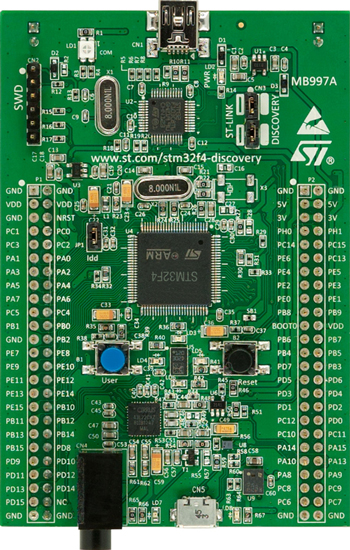
Key Features
- STM32F407VGT6 microcontroller featuring 32-bit ARM Cortex-M4F core, 1 MB Flash, 192 KB RAM in an LQFP100 package
- On-board ST-LINK/V2 with selection mode switch to use the kit as a standalone ST-LINK/V2 (with SWD connector for programming and debugging)
- Board power supply: through USB bus or from an external 5 V supply voltage
- External application power supply: 3 V and 5 V
- LIS302DL or LIS3DSH ST MEMS 3-axis accelerometer
- MP45DT02, ST MEMS audio sensor, omni-directional digital microphone
- CS43L22, audio DAC with integrated class D speaker driver
- Eight LEDs:
- LD1 (red/green) for USB communication
- LD2 (red) for 3.3 V power on
- Four user LEDs, LD3 (orange), LD4 (green), LD5 (red) and LD6 (blue)
- 2 USB OTG LEDs LD7 (green) VBus and LD8 (red) over-current
- Two push buttons (user and reset)
- USB OTG FS with micro-AB connector
- Extension header for all LQFP100 I/Os for quick connection to prototyping board and easy probig
Here's a consolidated list of steps to get up and running. Please see my earlier tutorial series for a full explanation of each step and what it does.
Continue reading Getting Started with the ARM GCC Compiler on Windows for the STM32F4DISCOVERY Board